Materials List:
1 pce 40mm x 40mm x 430mm square steel tube
1 pce 50mm x 50mm x 118mm square steel tube
1 pce 50mm x 5mm x 190mm flat mild steel
2 pcs M8 allen key bolts 15mm long
2 pcs M8 Threaded rod 160mm long
1 pce 30mm x 30mm x 110mm steel angle
1 pce 7mm thick laminated plywood 160mm x 110mm
2 pcs M8 hex shaped nylock nuts
2 pcs 40mm round head screws
1 pce 36mm x 36mm x 150mm plywood
2 pcs 10mm x 2mm x 118mm flat mild steel
1 pce M4 15mm long round head bolt
Please note. Watch the Youtube build video to better understand this tutorial.
STEP 1:
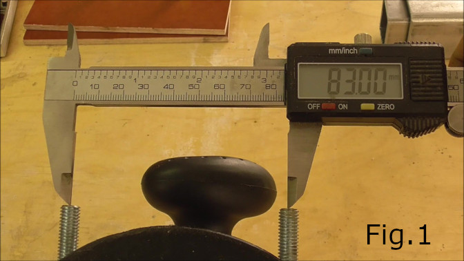
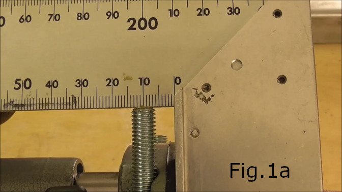
The first step is to cut all the materials to size. This project is based on the Makita RT0701C trim router plunger kit. In the video I use the cordless XTR01Z router with the plunger for the RT0701C. If you are using another type and make of router the dimensions may be different. With the RT0701C plunger the critical dimensions can be seen in Fig.1 & Fig.1a. The 8mm rods are 83mm apart from center to center and 10mm above the base. The length of the main steel tube determines the size of circle you can cut. In my case the 430mm length enabled a large enough radius to cut a 650mm diameter circle. If needed.
STEP 2:
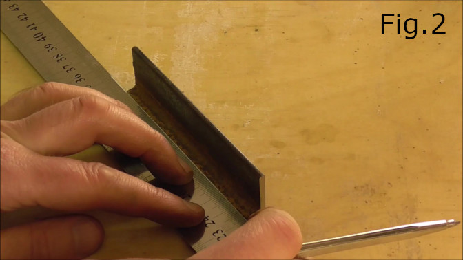
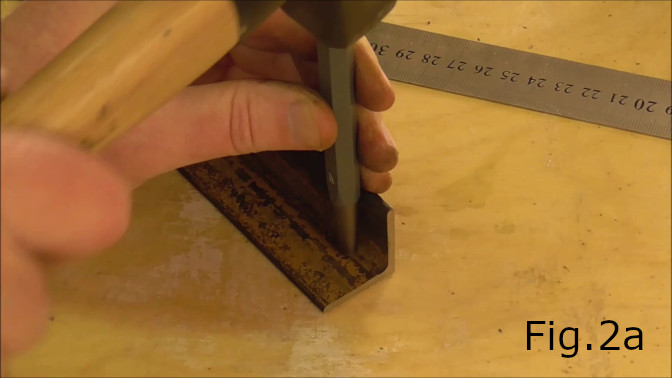
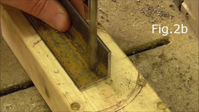
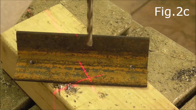
Take the 30mm x 30mm x 110mm steel angle and mark and drill the holes for the M8 rods 83mm apart and 10mm up from the base(Fig.2,Fig.2a,2b and 2c). Drill the holes with a 7.5mm drill bit so the holes can be threaded for the M8 rods.
STEP 3:
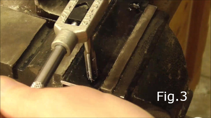
Thread the holes drilled in step 2 with an M8 tap(Fig.3).
STEP 4:
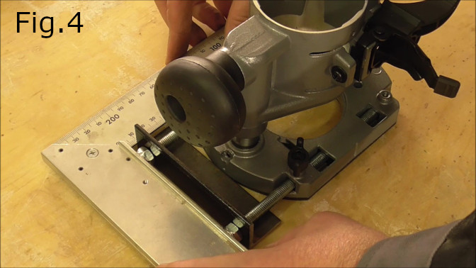
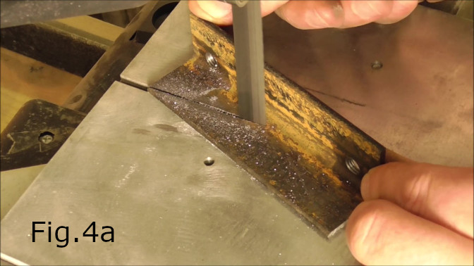
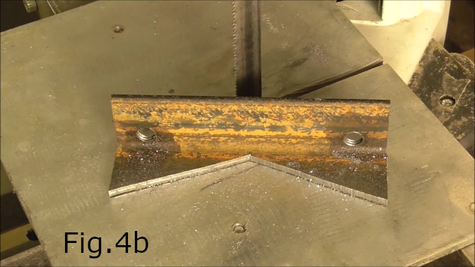
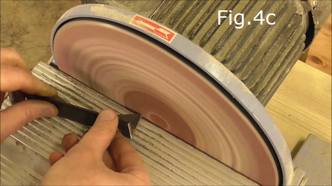
Next to reduce the length of the laminated plywood base and bring the steel angle closer to the plunger base. I decided to cut away the unnecessary part of the steel angle which can be seen in Fig.4. Using the bandsaw I cut from the outside corner straight to the center of the angle 20mm in from the front edge of the angle(Fig.4a and 4b). After this I cleaned up the part on the disc sander(Fig.4c)
STEP 5:
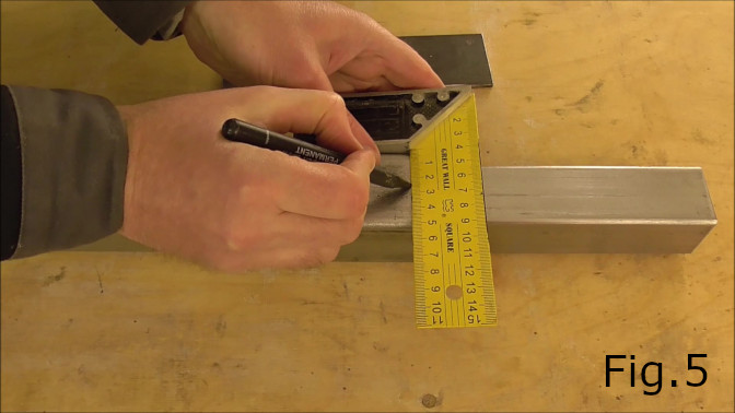
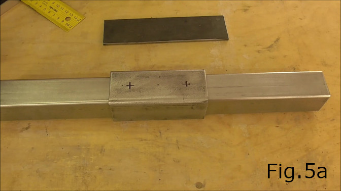
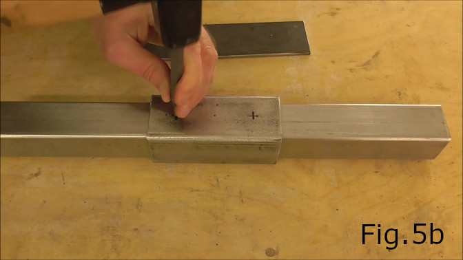
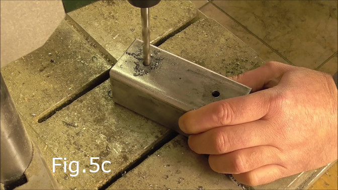
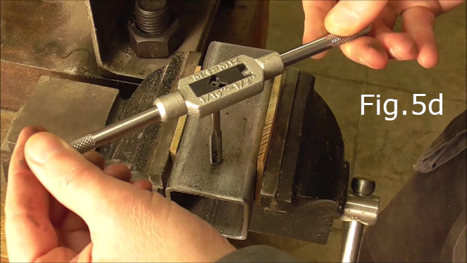
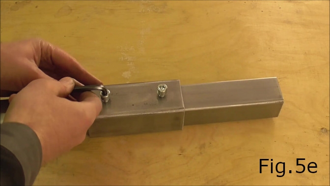
Mark, drill and tap holes for the M8 allen key bolts in the 118mm long square tube(Fig.5,5a,5b).Drill the holes centered approximately 25mm from each end of the tube(Fig.5c) using a 7.5mm drill bit. Tap the holes and test fit the 15mm M8 bolts(Fig.5d,5e).
STEP 6:
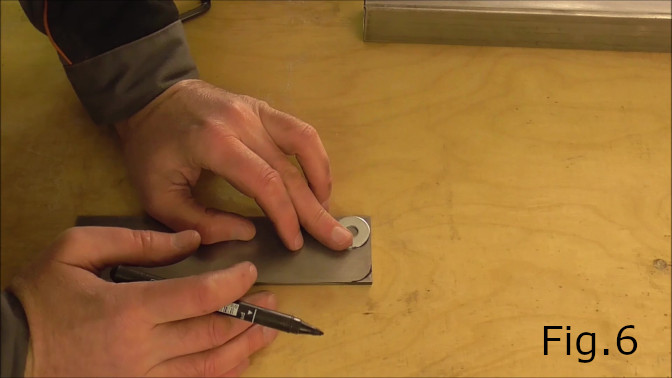
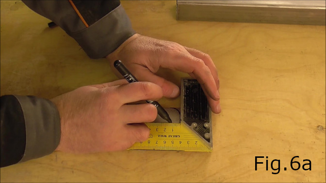
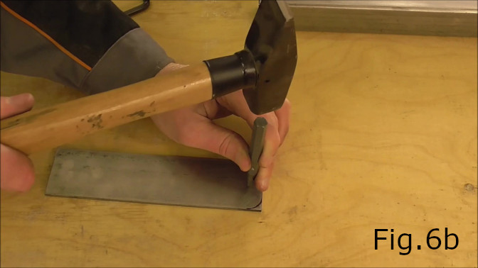
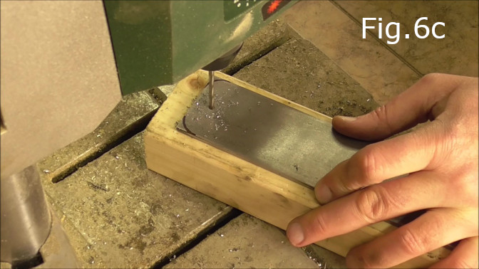
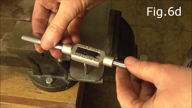
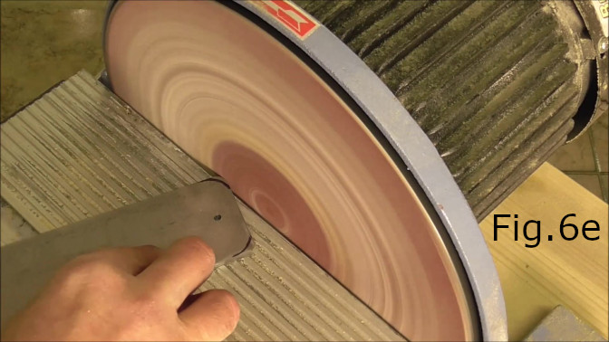
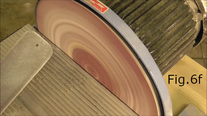
In the video I decided to round the corners on the 190mm flat steel(Fig.6,6e,6f) however rounding the corners is not necessary it was mostly done for aesthetic reasons. Next mark a hole approximately 12mm from one end(Fig.6a,6b) and in the center of the 190mm flat steel. Drill the hole with a 3.5mm drill bit(Fig.6c) and tap with an M4 tap(Fig.6d). The hole will be for the pivot.
STEP 7:
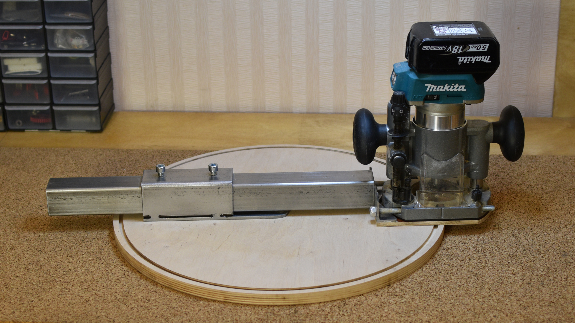
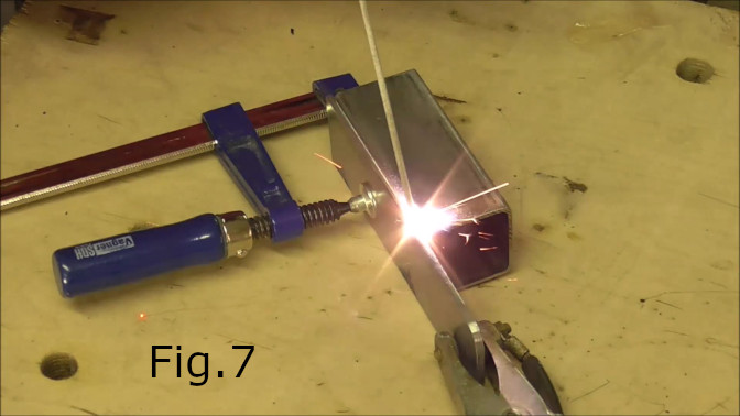
Weld the 190mm Flat steel to the 118mm tube. Align one end of the flat steel flush with one end of the 118mm tube. Make sure to clamp the flat piece to the bottom side of the tube(Fig.7). The holes drilled in Fig.5c are on the top side of the tube. Fixing the the tube to the flat steel requires only small welds and small welds ensure the steel does not warp. In the video I welded the pieces together in four places as can be seen in the photo at the top of this page. After welding I used the grinder to clean up the welds and made them flush with the steel tube.
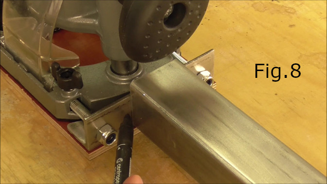
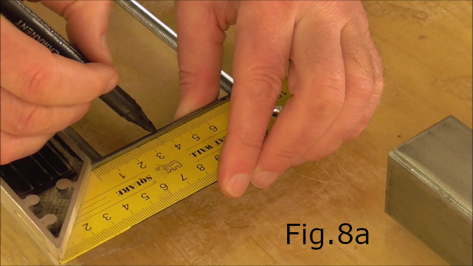
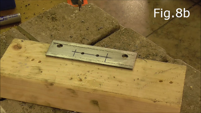
STEP 8:
Slide the 118mm tube over the main 40mm tube and fix in place with the two m8 bolts like in Fig.5e. Next place the laminated plywood piece under the plunger base with the angle made in steps 2 to 4 bolted to the plunger base as can be seen in Fig.8. Place the main 40mm tube so that it is hard up against the angle and mark the height at which you want the screws holes to be located in the 30mm steel angle. Next mark the center point on the angle(Fig.8a) and then 10mm from the center point to the left and the right make a mark for the screw holes. Drill the screw holes so they look something like Fig.8b. These holes were for 4mm diameter screws.
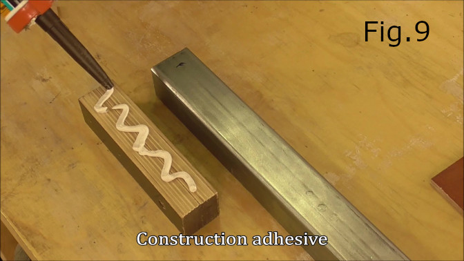
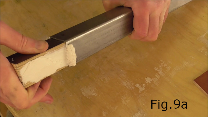
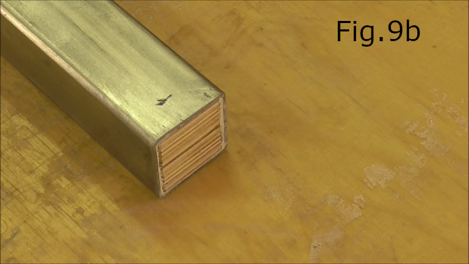
STEP 9:
Take the 36mm x 36mm x 150mm plywood piece and test fit inside the 40mm steel tube. If the plywood is too tight sand the plywood until it easily fits inside the tube. You want to allow some room for the adhesive. Once it fits, apply the construction glue on both sides and push it into the end of the tube that will be attached to the steel angle as in Fig.8. Make sure the plywood is flush with the end of the steel tube(Fig.9b). Allow 24 hours for the adhesive to set.
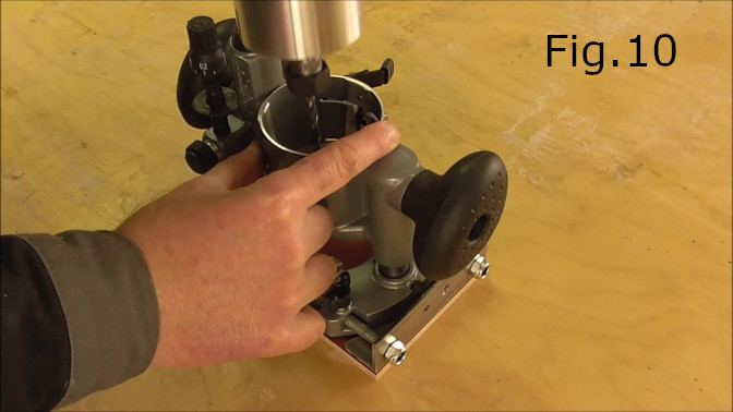
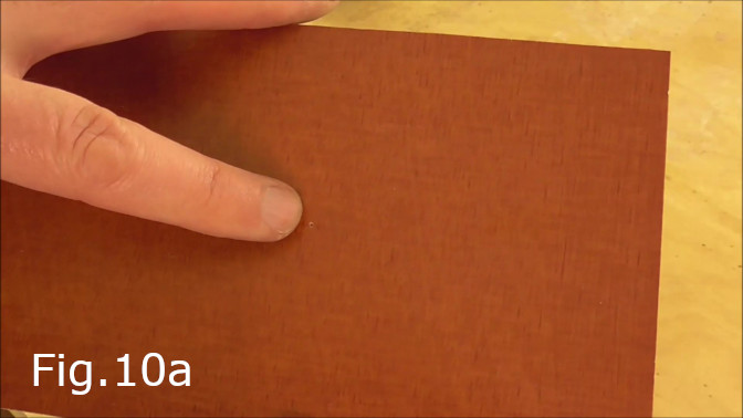
STEP 10:
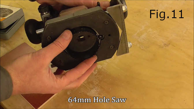
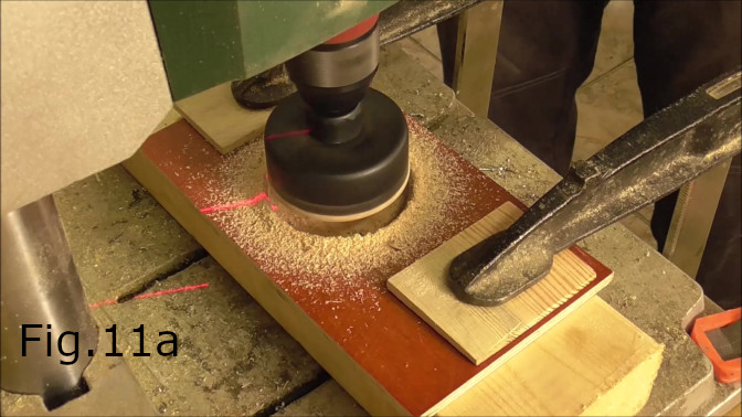
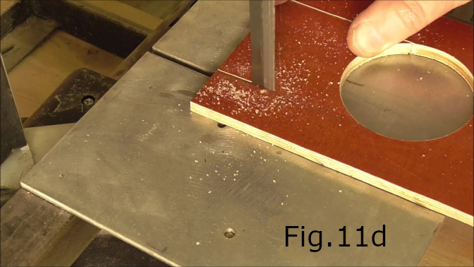
Next with the 160mm x 110mm laminated plywood aligned flush with the plunger base(Fig.10). Mark the center hole using the router with a sharp drill bit inserted into the router chuck. Place the router into the plunger until the drill bit punches a hole in the plywood(Fig.10a). After marking the center point use a 64mm hole saw to cut out the center hole(Fig.11,11a).
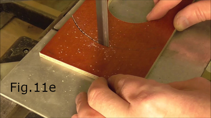
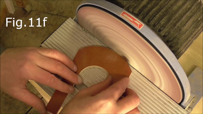
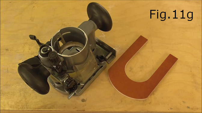
STEP 11:
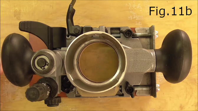
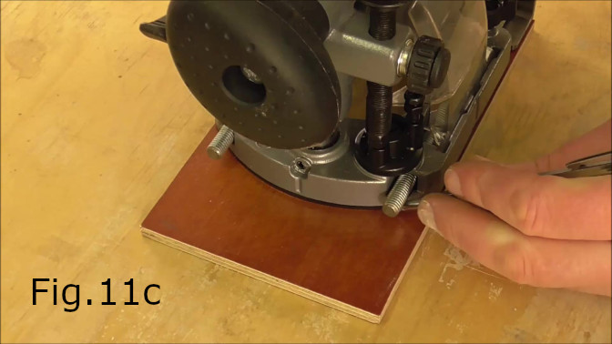
Check that the center hole aligns properly with the center hole in the plunger(Fig.11b). Next mark out the edge of the plunger base on the plywood(Fig.11c). Using a bandsaw or jigsaw cut away the unnecessary parts of the plywood(Fig.11d,11e). The plywood piece should look like Fig.11g. In the video I smoothed the edges on the disc sander(Fig.11f).
STEP 12:
Glue the steel gibs to the inside of the 118mm steel tube. Take the 10mm x 2mm x 118mm flat mild steel pieces and clean them with acetone. After cleaning I used a two part steel bonding epoxy to adhere the gibs to the tube walls(Fig.12,12a). Clamp the gibs in place(Fig.12b). Prior to glueing the gibs in place I spent some time sanding the gibs and test fitting so the 50mm tube would slide relatively easily over the main 40mm tube. Allow 24 hours for the epoxy to set.
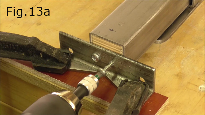
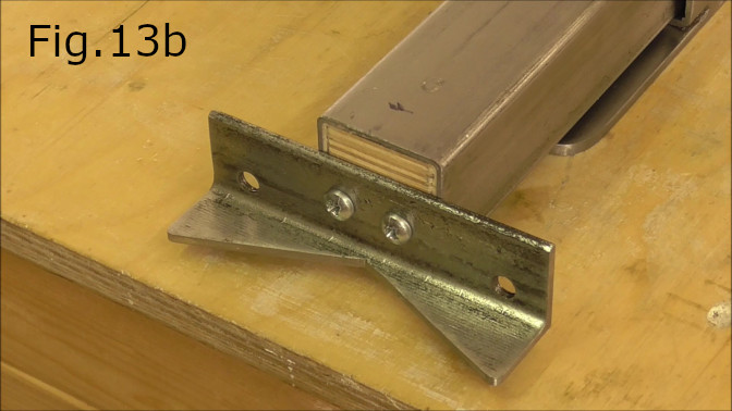
STEP 13:
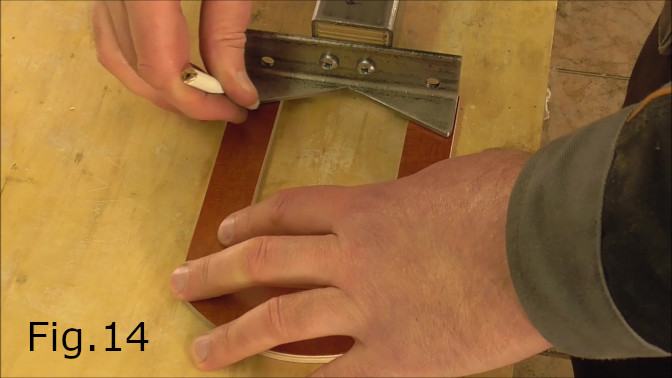
Attach the 30mm x 30mm steel angle to the main 40mm tube. Align and clamp down the angle and the main tube(Fig.13). Place a piece of 7mm laminate underneath the angle to endure the angle will be attached at the correct height. Drill holes for the round head screws. Screw the angle in place(Fig.13a). Once screwed in place take the plywood base made in step 11 and mark the areas that will be glued to the steel angle(Fig.14).
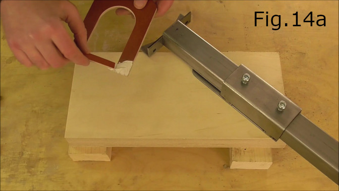
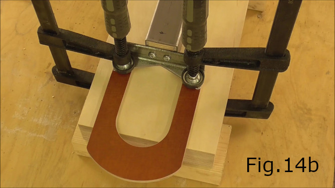
STEP 14:
Lightly sand the areas of the plywood that will contact the steel angle. Clean after sanding and apply the construction adhesive(Fig.14a). Align the plywood base to the steel angle and clamp in place(Fig.14b). Allow at least 24 hours for the adhesive to set.
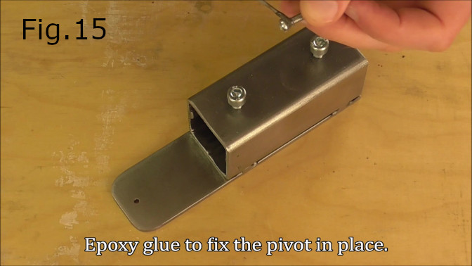
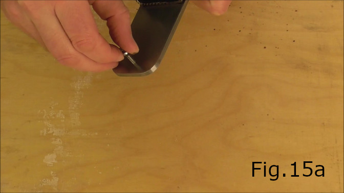
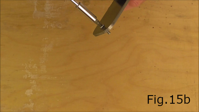
STEP 15:
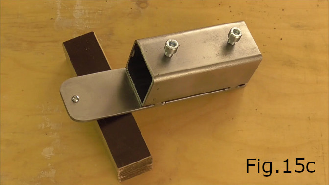
Take the M4 round head bolt, apply a two part metal epoxy to the thread of the bolt close to the bolt head(Fig.15). Screw the bolt into the pivot hole (Fig.15a,15b) and allow 24 hours to set(Fig.15c).
STEP 16:
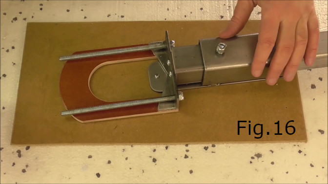
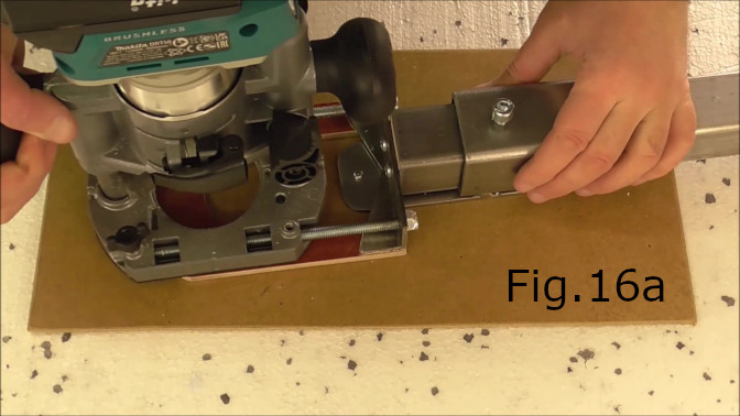
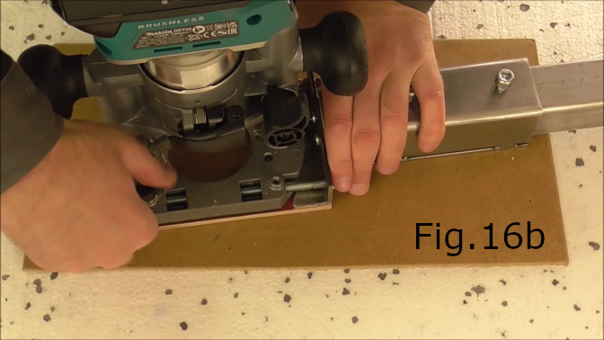
Once the pivot has set, screw in the M8 threaded rods into the steel angle and fasten with the m8 nylock nuts(Fig.16). Next attach the router and plunger to the circle jig(Fig.16a,16b). Now we are ready to cut a circle.
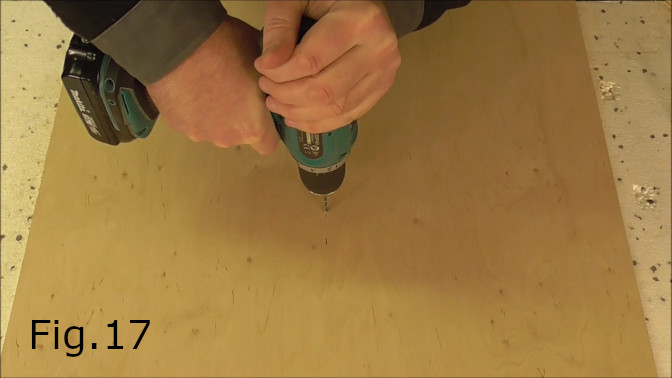
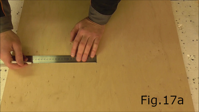
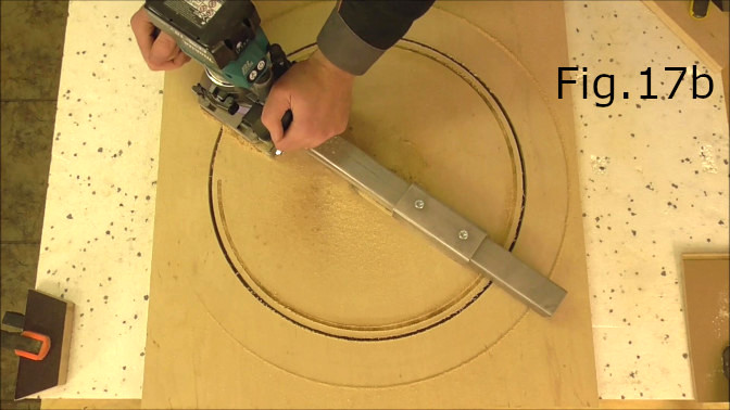
STEP 17:
The first step to cut a circle is drill the center hole with a 4mm drill bit into the work piece(Fig.17). Next measure the radius required for the size of circle you need to cut and mark on the work piece(Fig.17a). Place the circle jig in the center hole and adjust so the inside edge of the router bit is on the radius you marked. Tighten the M8 bolts to fix the jig at the correct length and begin cutting (Fig.17b).