Materials List:
2 pcs 33.7mm Diameter steel pipe 2.9mm wall thickness(No.1 fixed pipe-length=990mm – No.2 adjustable pipe-length =1080mm).
4 pcs Plywood Vertical supports for the pipes-205mm H x 45mm thickness
(2 pcs 165mm Wide-Fixed pipe supports. 2 pcs x 155mm wide adjustable pipe supports. To cut the corner chamfers for all 4 supports measure 40mm from the top corners both horizontally and vertically and draw a line joining both points).
1 pce 16mm plywood sheet 600mm W x 990mm L
1 pce 16mm plywood piece for saw stop – 400mm x 54mm 1 pce 16mm plywood angle cutting guide – 400mm x 52mm
1 pce Circular Saw – Saw blade = 185mm. Steel base plate of saw 280mm L x 140mm W. Remove the retracting blade guard from the saw.
2 pcs Steel L angles 30x30mm 358mm Long.
2 pcs Laminated 18mm plywood 283mm L x 105mm W
2 pcs Pine Stud 70mm H x 45mm W x 283mm L.
2 pcs Pine stud 70mm H x 45mm W x 800mm L.
2 pcs Pine Stud 95mm x 45mm x 600mm L.
1 pce Pine Stud 70mm x 45mm x 460mm L.
2 pcs M8 Hex head bolts 70mm. 1 pce M8 Hex head bolts 45mm. 1 pce M10 Hex head bolts 45mm. 10 pcs M8 Hex head bolts 100mm.
4 pcs M8 Hex head bolts 80mm L. 4 x M10 washers. 10 x M8 Long hex nuts (24mm L)
16 pcs Abec 7 Carbon steel Skateboard ball bearings(M8 bolts fit inside)
22 pcs M8 Nyloc nuts. 8 x M8 standard nuts. 8 x 110mm Torx head screws.
4 pcs 40mm L x 25mm W x 3mm Thick steel used for brackets
1 pce 123mm L x 25mm W x 3mm Thick steel
4 pcs 61mm L x 25mm W x 3mm Thick steel.
26 pcs 45mm Countersink head Timber screws
14 pcs 25mm x 4mm timber screws
2 pcs 15mm x 4mm timber screws 3 pcs 10mm x 4mm timber screws 12 pcs 15mm x 4mm countersink head timber screws 4 pcs M5-10mm L Round head hex socket bolts.
The clamps are not included in this list only the nuts and bolts used for the 2 end clamps.
The Clamps could be made of metal or something else other than plywood. The end clamps are 45mm H x 130mm L.
Please note. Watch the Youtube build video to better understand this tutorial.
STEP 1:
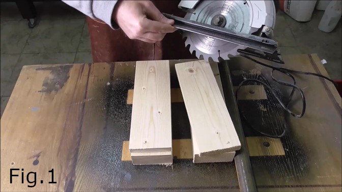
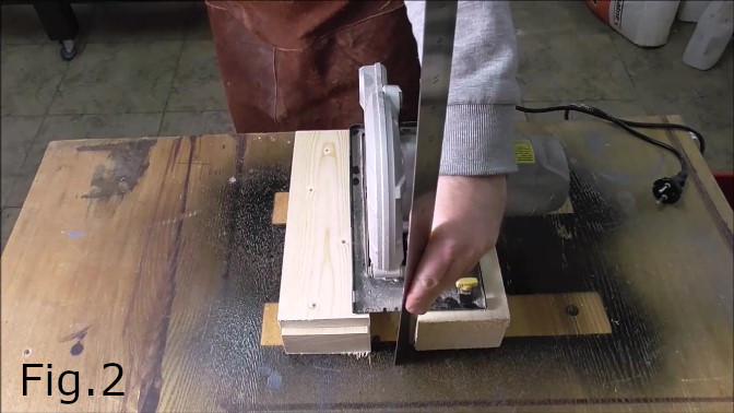
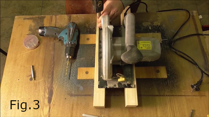
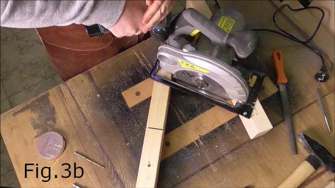
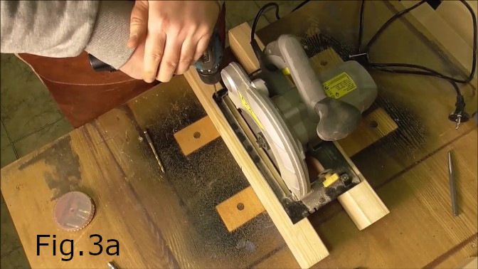
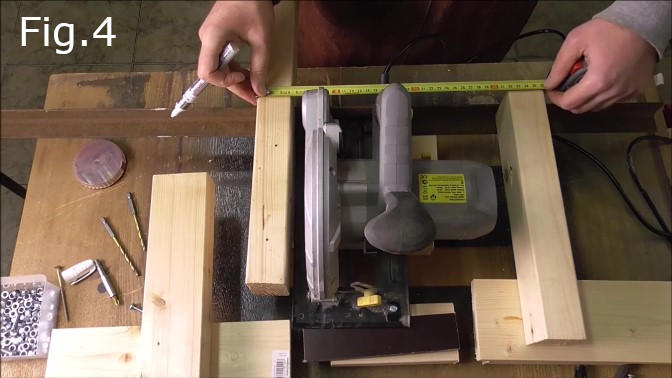
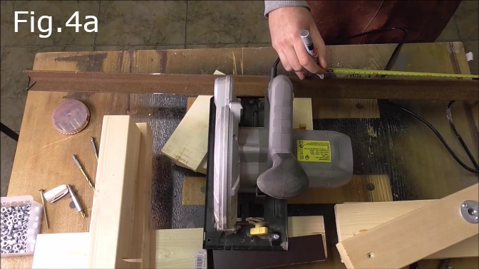
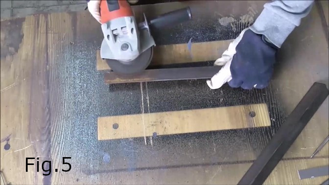
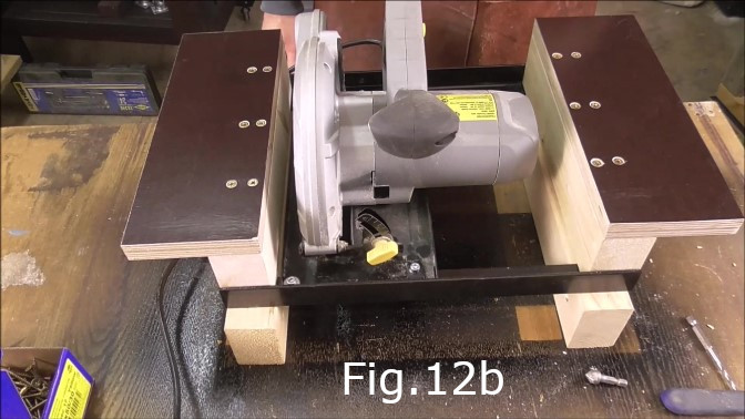
First, before cutting the materials from the materials list above, measure the dimensions of your circular saw(Fig.1 & Fig.2). The dimensions of your saw may vary from my saw dimensions which means the dimensions in the materials list will not work for your saw. The circular saw I used has a 185mm diameter blade and the base plate is 280mm long and 140mm wide. The overall width including the motor is approximately 260mm. The width of the motor together with the 45mm wide pine studs meant the 30x30mm steel angles in Fig.4,4a,Fig.5 and Fig.6 were cut to 358mm lengths. The blade diameter of your circular saw will affect the height the pipe rails are attached to the plywood supports(Fig.25,26,26a). For instance a 210mm blade as opposed to a 185mm blade would mean that the pipes and carriage should be 12mm higher above the cutting table to make use of the larger diameter cutting blade. Once you have measured your saw and cut the materials accordingly to size, the next step is to drill holes in the saw base plate so the circular saw can be attached to the carriage(Fig.3,3a,3b). In the video I only drilled 3 holes as I used the existing hole for the rip fence as the fourth hole.
STEP 2:
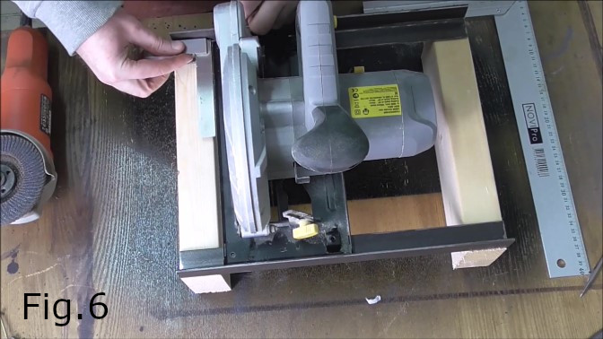
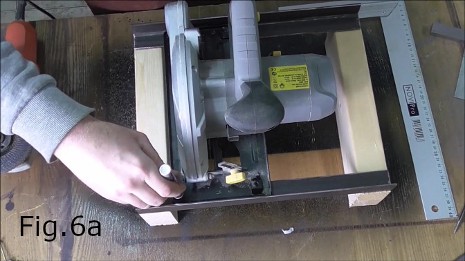
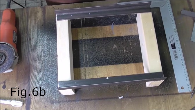
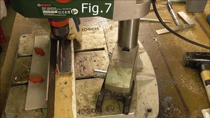
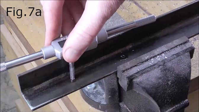
Next place the 30x30mm angles on top of the 70x45x283mm pine studs(fig.6). Square the angles with the studs and make sure the ends of the angles are flush with the outside edges of the studs(Fig.6a). Place the saw on top of the angles in the position where the saw will be finally located in the carriage(Fig.6a). Check for Squareness(Fig.6). Allow clearance between the motor fan and the stud of at least 10mm(For ventilation see Fig.12b). Once the saw is squared up, mark the hole locations in the saw base onto the Steel angles(Fig.6a,6b). Drill the holes in the 30x30mm steel angles with a 4.5mm drill(Fig.7) and tap the holes using an M5 tap(Fig.7a).
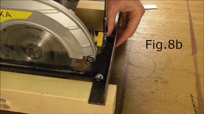
STEP 3:
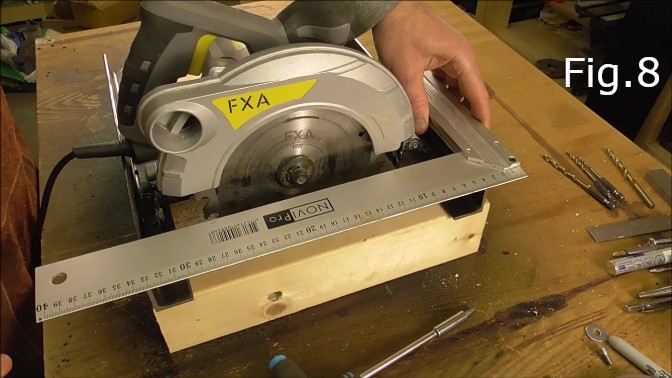
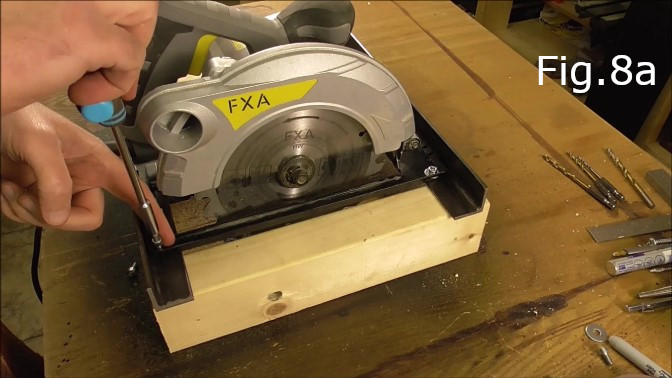
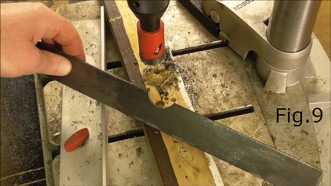
Test fit the saw. Check for squareness and screw in the M5 bolts(Fig.8 & Fig.8a,8b). While the saw is attached to the steel angles mark the location of the electric cable(if your saw is mains powered). On my saw the cable is hard up against the steel angle so I marked the location and using a hole saw I cut out a notch from the angle to make room for the electric cable(Fig.9).
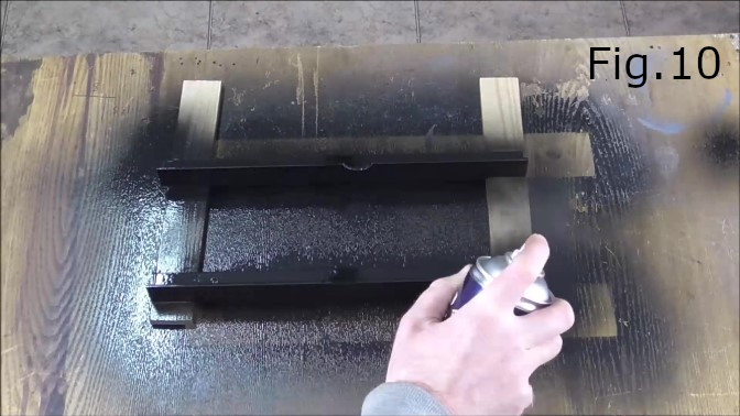
STEP 4:
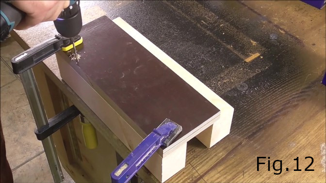
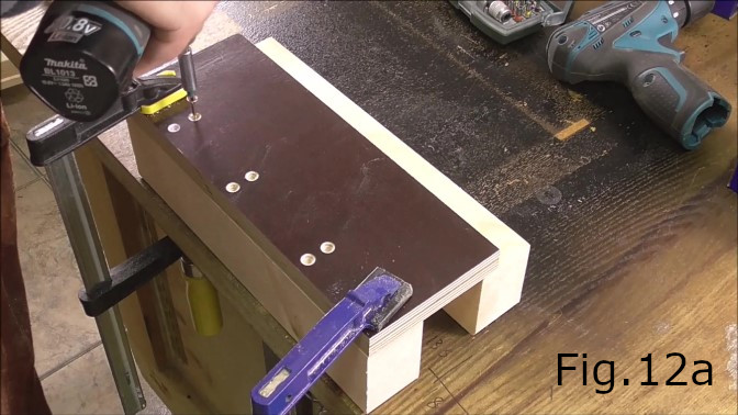
After drilling and tapping the 30mm steel angles, clean them and apply paint(Fig.10). Next clamp the laminated 18mm plywood pieces(283mm x 105mm) to the 283mm pine studs(Fig.12). Drill and countersink six holes for six 45mm timber screws(Fig.12a). Make sure to leave at least 40mm of space on each end of the plywood pieces so the bolt holes can be drilled as seen in Fig.18d. Screw the plywood to the studs. You should now have two sides of the saw carriage assembled(Fig.12b).
STEP 5:
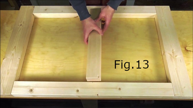
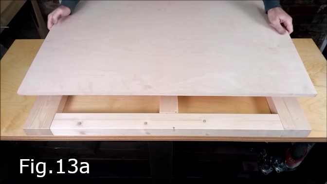
Assemble the jig table. Place the 2 pine studs 95mm x 45mm x 600mm and the 2 pine studs 70mm x 45mm x 800mm as can be seen in Fig.13. The 90x45mm studs are placed on the ends to the left and right in Fig.13 with the 70mm x 45mm x 800mm pieces forming the long sides. The 70mm x 45mm x 460mm pine stud is placed in the center as a support piece for the plywood sheet. Once the pieces are all tightly fitted together nice and square, carefully place the 16mm plywood sheet 600mm x 990mm over the top(Fig.13a). Make sure the edges are all flush with the studs underneath then clamp in place(Fig.13b). Drill and countersink for 45mm timber screws. Use screws only on the outside frame.

STEP 6:
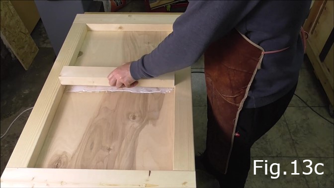
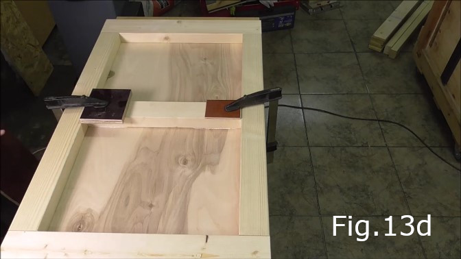
Once the plywood sheet is screwed on to the frame, remove the clamps and turn over the base. Glue and clamp the 70mm x 45mm x 460mm pine stud in the middle of the plywood sheet(Fig.13c,13d).
STEP 7:
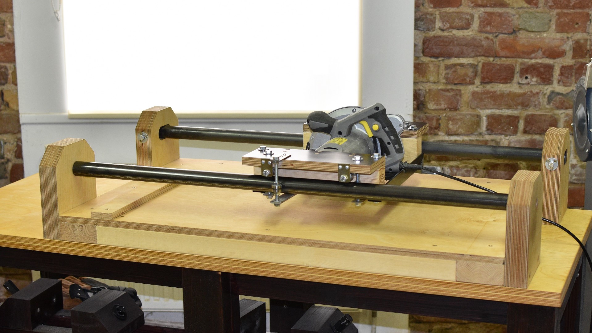
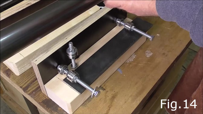
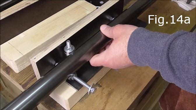
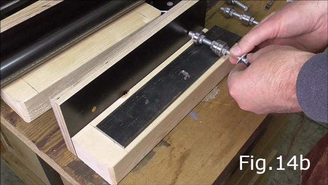
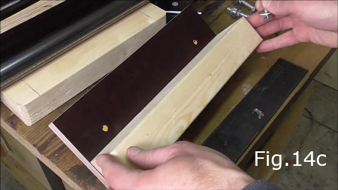
Mark the holes for the vertical carriage bearings. Assemble two bearings onto each of two of the M8 bolts and place a 4mm thick piece of steel onto the pine studs(Fig.14). The studs make both sides of the saw carriage as seen in Fig.12b. The steel plate seen in Fig.14 is a spacer to make sure there is clearance between the bearings and the studs once the bearings are bolted in place. In Fig.14a I was using one of the pipes to test where the pipes/rails would be located in relation to the carriage so I could calculate at what height I would need to attach the pipes to their supports. Next I put some paint on the end of one of the bolts and with the bearings placed flat on the steel plate marked the holes for the M8 bolts approximately 50mm from each end of the plywood(Fig.14b,14c). For the other side of the carriage only the rear vertical bearings are needed so only one hole should be marked and drilled. In the video I drilled two holes for vertical bearings on each side of the carriage but later moved the right front vertical bearings to the left side of the carriage running on the outside of the pipe as can be seen in the cover photo at the top of this page. Making the carriage easier to align.
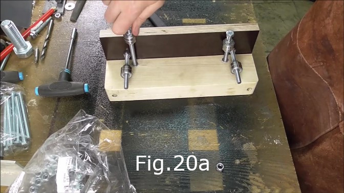
STEP 8:
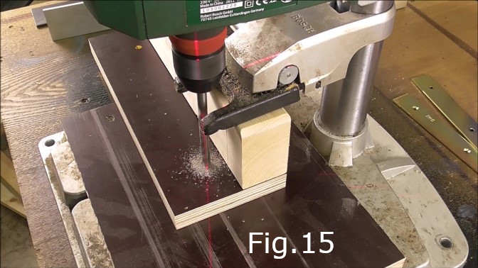
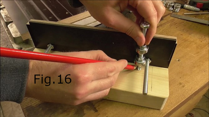
Drill the holes where marked completely through the plywood with an 8mm diameter drill bit(Fig.15). Make sure you have another piece of wood underneath the plywood when drilling to avoid tear out. Once the holes are drilled take two of the M8 x 100mm bolts and fasten them in place in the newly drilled holes each with an M8 nut, as seen in Fig.16. Next measure the location of horizontal bearing bolts. Place the 4mm steel hard up against the laminated plywood(Fig.16), then place one of the bolts with the bearings hard up against the 4mm steel plate and as close as possible to the 100mm vertical bearing bolts allowing for clearance. The two horizontal bearing bolts are located on the inside of the vertical bolts(Fig.20a).
STEP 9:
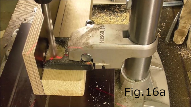
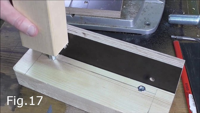
Drill the holes for the horizontal bearing bolts. Two holes in each side of what will be the saw carriage(Fig.16a). I used a 12mm drill bit to make the holes slightly smaller than the width of the M8 Long hex nuts. Drill the holes to the same depth as the length of the Hex nuts. In this case the Hex nuts were 24mm in length. Next using a block of wood hammer the hex nuts into the holes so they are flush with the surface(Fig.17).
STEP 10:
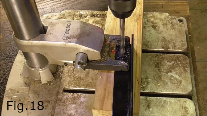
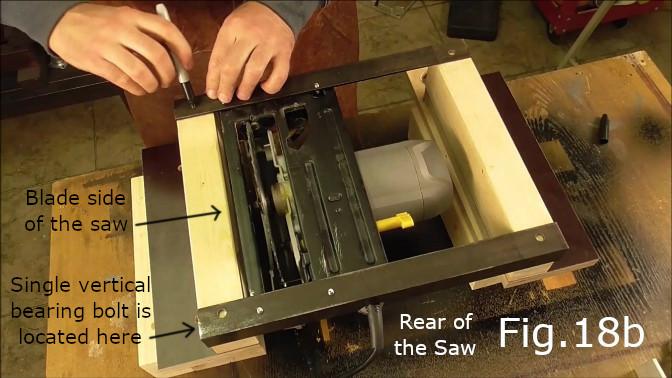
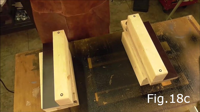
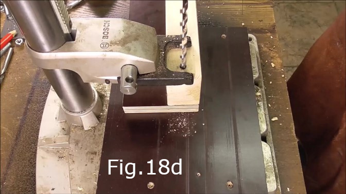
Take the 30x30mm steel angles used in Step 2 and drill an 8mm hole 22mm from each end(Fig.18). Next place the sides of the saw carriage upside down on some blocks(Fig.18b, Fig.18c). Screw the saw to the 30x30mm angles using the holes drilled in Step 2. Turn the saw and attached angles upside down and place on the pine carriage pieces(Fig.18b) so they are flush with the outside edges of the pine pieces. Make sure the side of the carriage with only one vertical bearing bolt is placed on the blade side of the saw(Fig.18b) with the single vertical bearing bolt at the rear end of the saw. Mark the location of the holes drilled in each end of the steel angles with a marker(Fig.18b,Fig.18c). Drill the four holes with an 8mm or 8.5mm drill bit. The drill bit needs to be at least 110mm long to drill through the pine and plywood(Fig.18d).
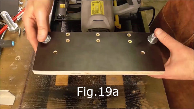
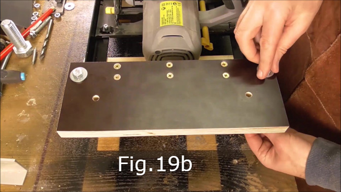
STEP 11:
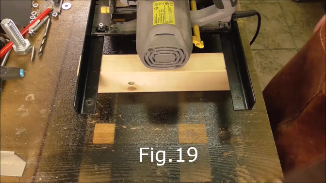
Test fit both sides of the carriage. Turn the saw right side up and place on wooden blocks(Fig.19). Test fit the bolts and bolt together(Fig.19a, Fig.19b). Check that the sides of the carriage once bolted together are vertical and square.
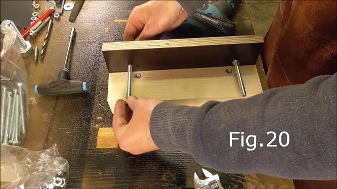
STEP 12:
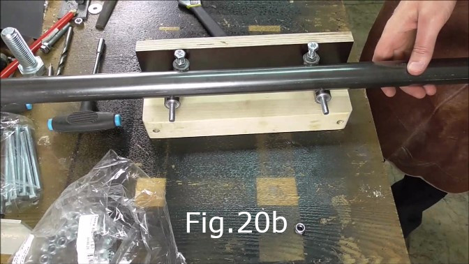
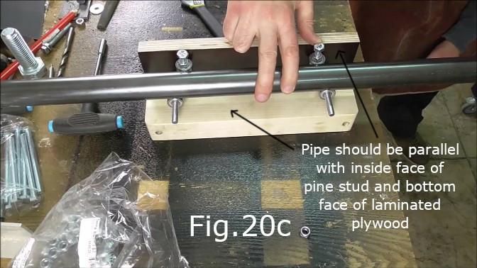
After test fitting unbolt the wooden parts of the carriage and install all the bearing bolts with the required bearings(Fig.20, Fig.20a). Each bearing bolt requires two ABEC 7 skateboard bearings. In Fig.20a you can see how the bearings are located and fixed in position with m8 hex nuts. The nuts closest to the heads of the bolts are standard hex nuts with the nuts closest to the end of the bolts being nyloc hex nuts. Use one of the steel pipes to determine the correct location of the bearings(Fig.20b). The bearings need to be in contact with the middle of the pipe. The pipe needs to be parallel with the laminated plywood surface and at the same time parallel with the inside face of the pine studs(Fig.20c) while all bearings are in contact with the middle of the pipe.
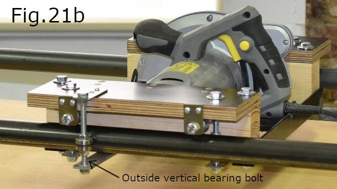
STEP 13:
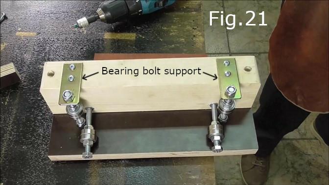
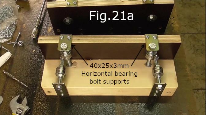
Once the bearings have been adjusted and fixed in place with the hex nuts, attach the bearing bolt supports(Fig.21). The bearing bolts are attached using the 25mm timber screws except for the upper support for the outside bearing bolt(Fig.21b) which requires the 15mm screws. For the vertical bearing bolt supports use three of the 61mm x 25mm x 3mm thick steel pieces seen in Fig.21. For the horizontal bearing bolts use the 40mm x 25mm x 3mm thick steel pieces(Fig.21a) and for the outside vertical bearings use one of the 61mm x 25mm x 3mm pieces for the top support and the 123mm x 25mm x 3mm piece for the bottom support(Fig.21b). Pre drill all the bearing support screw holes to make sure the supports are fixed accurately and do not detrimentally affect the alignment of the bearing bolts.
STEP 14:
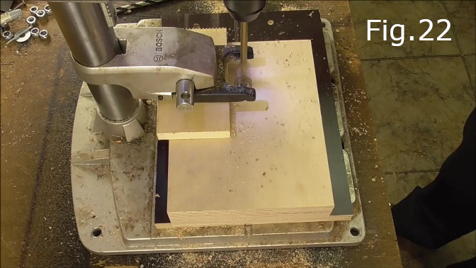
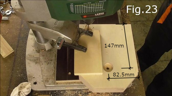
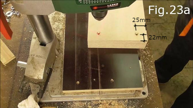
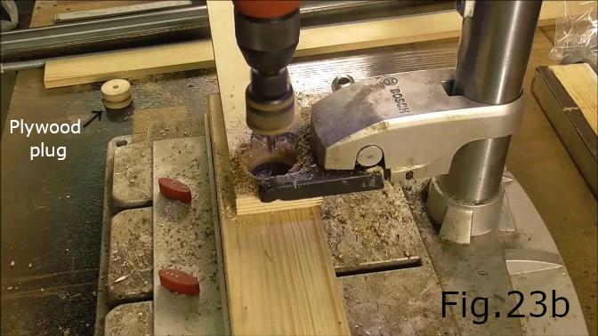
Prepare the fixed pipe supports. Take the two 205mm x 165mm x 45mm plywood pieces and drill a hole in each piece 147mm from one end and in the center of the piece(Fig.23). Drill the holes with an 8mm drill bit all the way through each piece. Next on one side of each of the supports drill a 25mm x 10mm deep recess using the existing 8mm hole as a pilot hole for a 25mm spade drill(Fig.22). The result should look like Fig.23. On the same side as the recessed bolt hole drill two holes near the base of each of the supports(Fig.23a) 22mm from the base and 25mm from the sides, for the Torx screws. Countersink the holes. Next using a 30mm hole saw with an 8mm drill bit, cut out two 15mm thick plywood plugs(Fig.23b).
STEP 15:
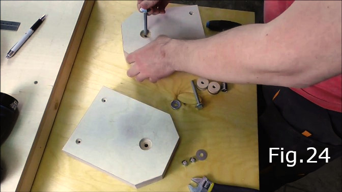
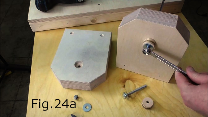
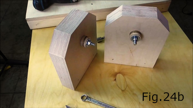
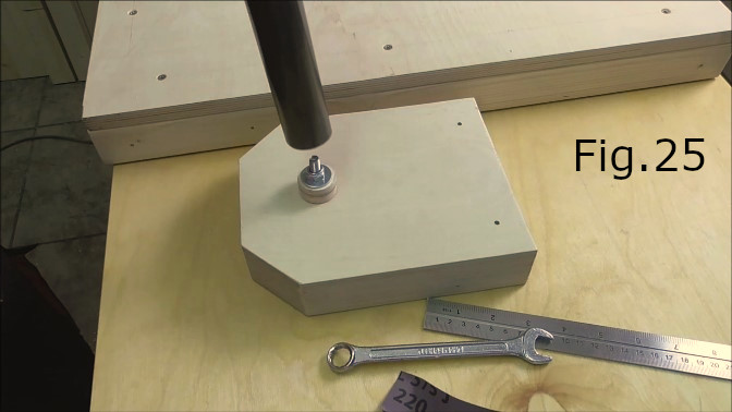
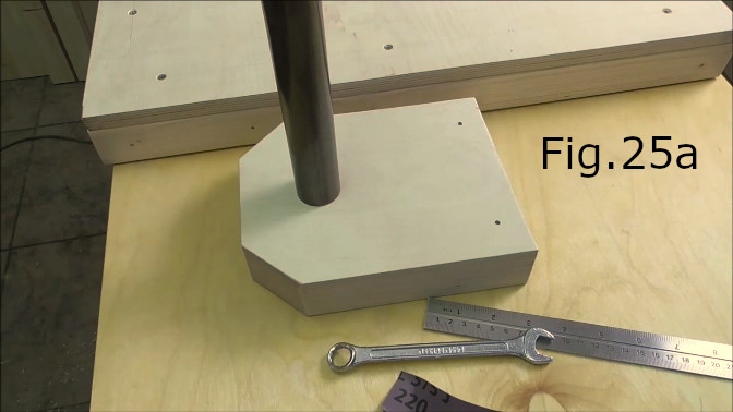
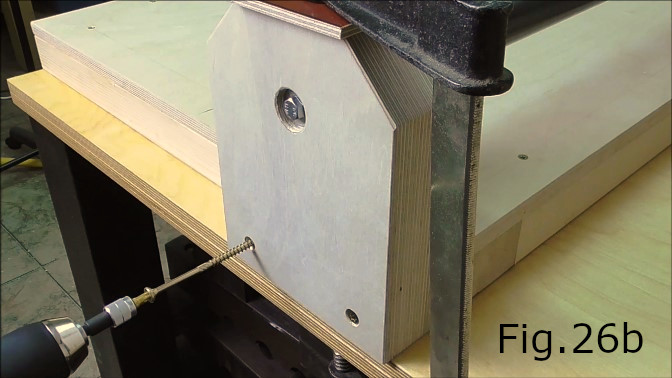
Using two 70mm M8 bolts attach the plywood plugs to the inside faces of each of the fixed pipe supports(Fig.24, Fig.24a, Fig.24b). The head of each bolt should sit inside the recesses drilled in step 14 as can be seen in Fig.26b. Use washers on both ends of each bolt and tighten with M8 nyloc nuts. Next take the 990mm long steel pipe and press fit one end of the pipe onto each of the pipe supports(Fig.25, Fig.25a) and over the plywood plugs. Note both ends of the pipe should be a tight fit over the plugs and should be pushed hard up against the face of each plywood support.
STEP 16:
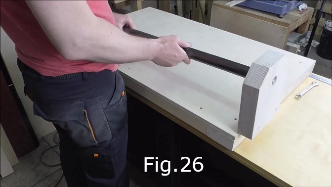
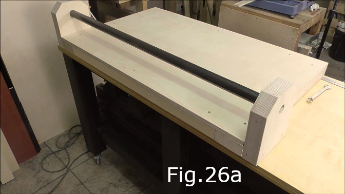
Place the assembled fixed pipe and supports over the cutting table(Fig.26, Fig.26a) making sure the outside edges of the pipe supports are flush with the outside edge of the cutting table. Clamp the cutting table and pipe supports in place then attach the supports to the table using the 110mm Torx screws(Fig.26b).
STEP 17:
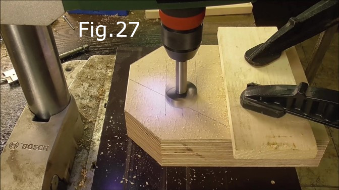
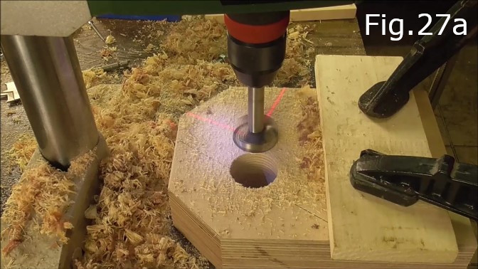
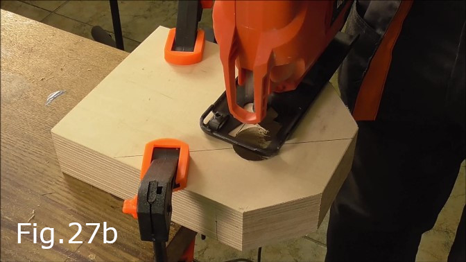
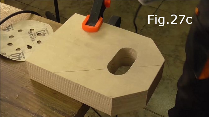
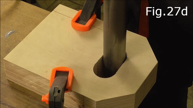
Prepare the adjustable pipe supports. On both the 205mm x 155mm x 45mm plywood support pieces measure 147mm from the base and draw a line parallel with the base. On this line 77.5mm from the left and right sides of each support mark the center point. Measure 17.5mm from the center point along the line on both sides of the center point and leave a mark. These two marks are the center points for drilling. Use a 35mm Forstner bit to drill two 35mm holes(Fig.27, Fig.27a). Both holes should be drilled along the line which is parallel to the base. Make sure to use a piece of wood underneath the supports when drilling to avoid tear out. Once both holes are drilled in each of the supports cut out the remaining material with a jigsaw to create one hole(Fig.27b, Fig.27c). Sand the holes smooth and check the fit with the remaining pipe(Fig.27d).
STEP 18:
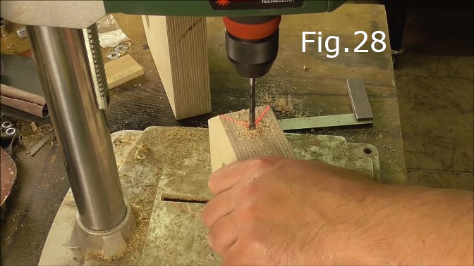
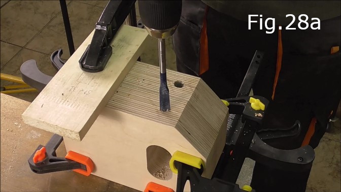
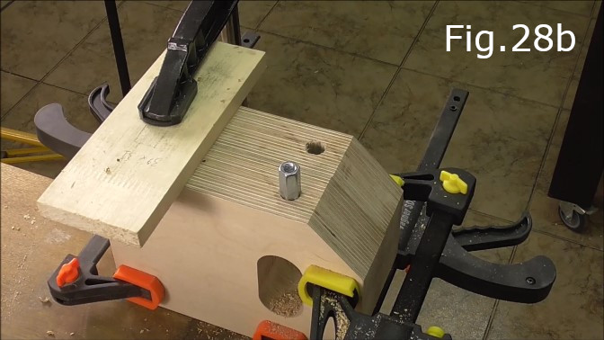
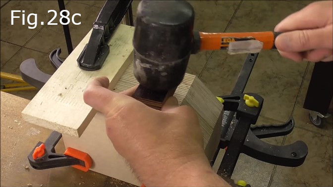
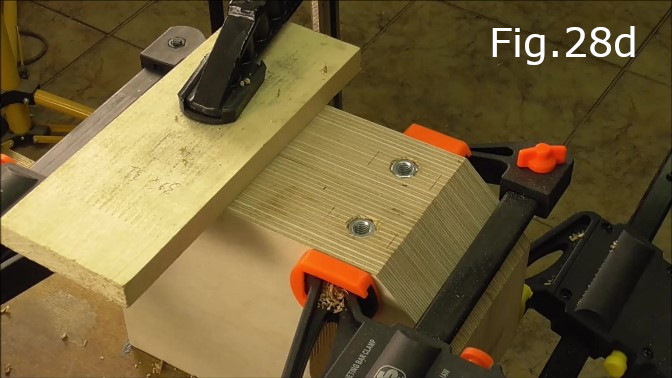
Drill the holes for the adjustment bolts in the sides of the pipe supports. Drill a pilot hole with a small diameter drill bit (3 or 4mm) in the center of each side (22.5mm from the edges) of both supports exactly 147mm from the base of each support(Fig.28). Drill the pilot holes right through each side of the supports. The holes should align with where the center of the pipe will be when sitting inside the supports as can be seen in the cover photo at the top of this page. Once the pilot holes are drilled use a 12mm spade drill to bore out the holes so they are slightly smaller than the width of the M8 hex nuts and the same depth as the length(24mm) of the hex nuts(Fig.28a). Make sure to drill the holes as straight and vertical as possible. Next hammer the nuts into the holes using a mallet and block of wood making sure to hammer them in at 90 degrees to the side of the plywood supports(Fig.28b, Fig.28c). The end result should look like Fig.28d. Do this for both sides of both supports.
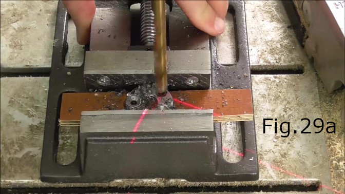
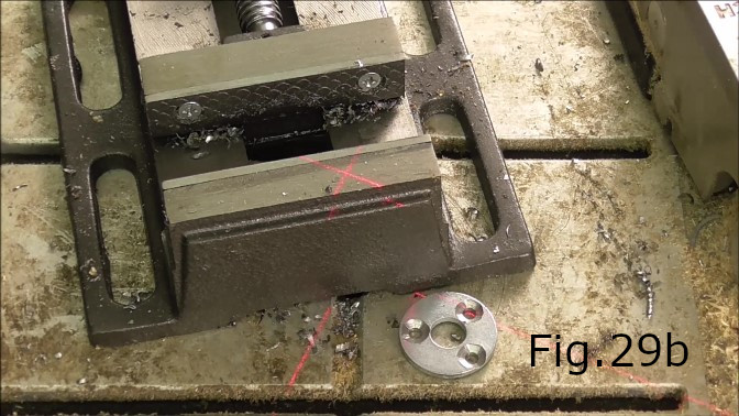
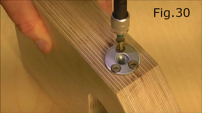
STEP 19:
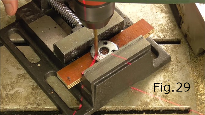
Drill three holes in each of the four M10 washers using a 4mm drill bit(Fig.29). Countersink the holes using a larger drill bit. In the video I used an 8mm bit(Fig.29a). Each of the four washers should look like the washer in Fig.29b. Next place one of the M10 washers over each of the previously inserted M8 nuts and screw them in place(Fig.30). The washers will keep the M8 nuts in place. Do this for all four of the inserted M8 nuts.
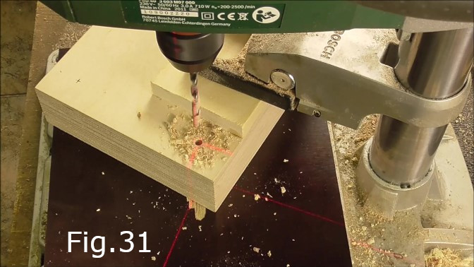
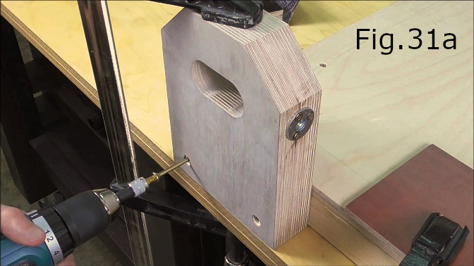
STEP 20:
Drill two holes near the base of each of the adjustable pipe supports (Fig.31) 22mm from the base and 25mm from the sides the same way as in step 14(Fig.23a). Drill the holes completely through the 45mm thick supports. Countersink the holes. Next clamp one of the supports to each end of the vacant side of the cutting table, flush with the table’s outside edge(Fig.31a). Make sure the cutting table is also clamped so nothing can move. Fix the supports to the cutting table using the remaining 110mm Torx screws(Fig.31a).
STEP 21:
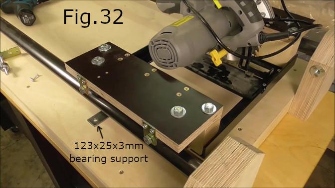
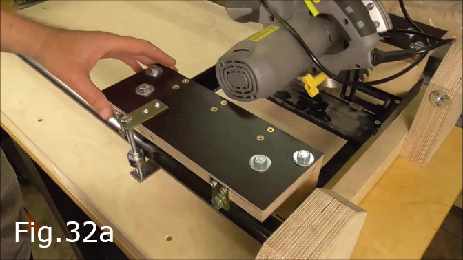
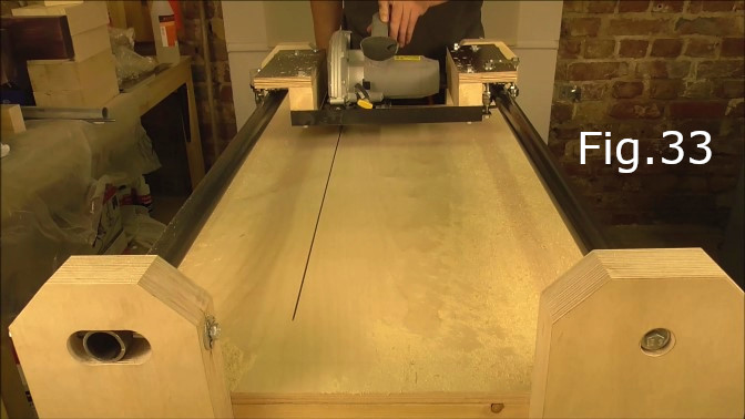
Place the 1080mm steel pipe into the supports and screw in the four M8 bolts used for adjusting the pipe alignment(Fig.33). Before placing the saw carriage onto the pipes attach the 123mm x 25mm x 3mm bearing bolt support to the underside of the carriage at right angles to the pine stud it is attached to(Fig.32). Next loosen the cut depth adjuster on the saw so the blade is in a shallow cut position, then tighten. Now the saw carriage can be placed onto the pipes. Place the left side carriage bearings hard up against the fixed pipe and then adjust the movable pipe accordingly so that the bearings on the blade side of the carriage are also in contact with the movable pipe. Once the carriage is in place move it from one end of the saw table to the other making sure the carriage does not bind and runs smoothly. Make sure the bearings stay in contact with the pipes along the length of travel along the pipes. Next attach the outside vertical bearing on the left side of the saw carriage(Fig.32, Fig.32a). First test fit the top 61mm x 25mm x 3mm vertical bearing support and mark the screw hole locations then drill the holes for the 15mm screws. Assemble the vertical bearing bolt with the top and bottom bearing bolt supports and screw the top support in place(Fig.32a) making sure the bearings are in contact with the pipe.
STEP 22:
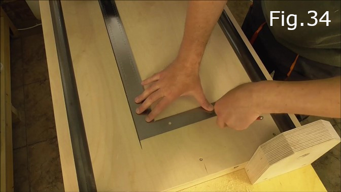
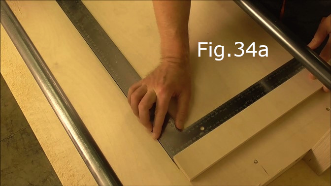
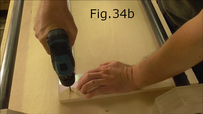
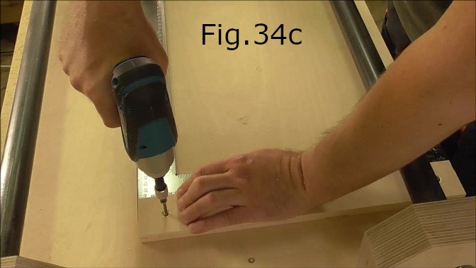
Now that the saw carriage is aligned and in place, make a cut for the saw blade in the cutting table. Pull the saw carriage back, so the rear of the carriage is hard up against the pipe supports at the back of the cutting table(Fig.33). Plug in the saw, press the trigger and while the saw is running slowly loosen the blade depth adjustment and push down the saw into its full depth of cut position without moving the carriage forward. Once the blade has cut into the table in the start position tighten the cutting depth adjuster and then slowly move the saw forward until you reach the other end of the table. Now there is a groove in the table for the cutting blade(Fig.33). Place a large set square against the cutting groove with the corner of the square about 25 to 30mm from the end of the cut(Fig.34). Make sure there are no gaps between the square and the cutting groove. Draw a 90 degree pencil line(Fig.34) this line marks the location for the 400mm x 54mm saw stop (Fig.34a). Place the saw stop exactly on the line and check that it is exactly 90 deg. square with the cutting groove. Make sure the saw stop end is flush with the outside edge of the table and drill screw holes at each end of the stop. Screw in place(Fig.34b, 34c).
STEP 23:
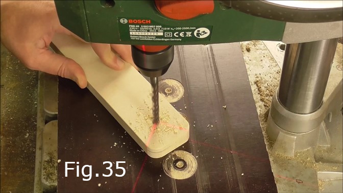
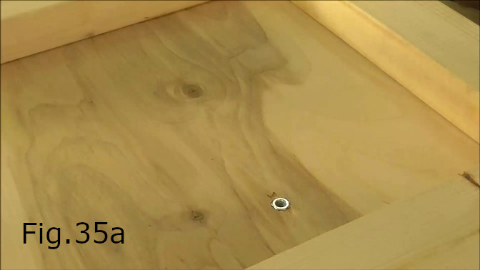
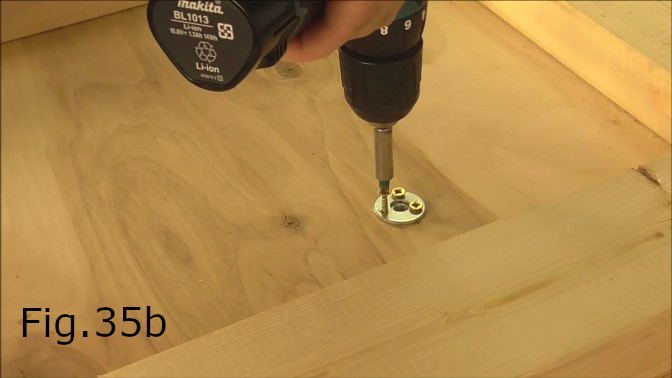
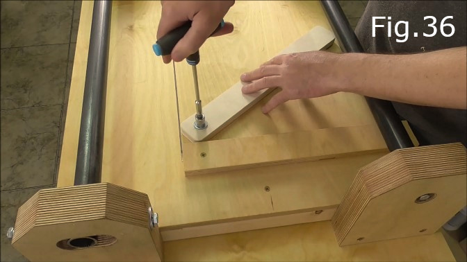
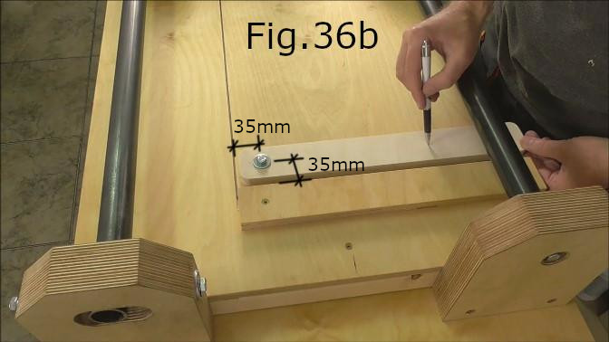
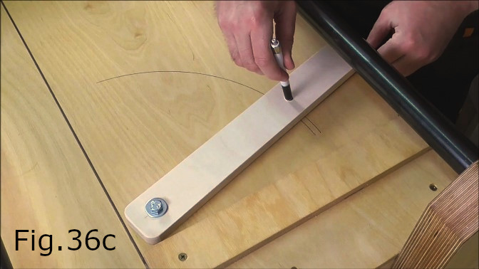
Make the angle cutting guide. Drill two holes in the 400 x 52 x 16mm plywood piece used for the angle cutting guide. The first hole should be drilled 30mm from one end of the guide with an 8mm drill bit(Fig.35). The second hole should be drilled 220mm from the center of the first hole with a 10mm drill bit. Round the corners of the angle guide on a disc sander. Next drill an 8mm hole in the cutting table 35mm from the saw stop and 35mm from the edge of the cutting groove(Fig.36b). On the underside of the table use a 12mm spade drill to widen the 8mm hole and make a recess deep enough for a standard M8 nut(Fig.35a). Using the 10mm x 4mm screws. Fix one of the M10 washers over the top of the M8 nut to hold the M8 nut in place(Fig.35b). Next on the top side of the table bolt on the angle guide(Fig.36) and with a pen or pencil mark the locations of both sides of the angle guide arc(Fig.36c).
STEP 24:
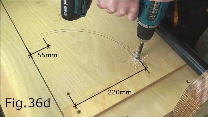
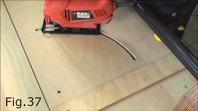
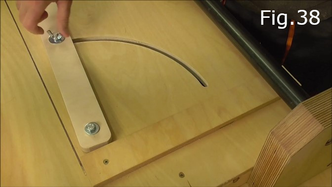
After marking the arc of the cutting guide, drill a 10mm hole at each end(Fig.36d). Using a jigsaw, cut out the 10mm wide slot(Fig.37). Sand the slot smooth with sandpaper. Install the M10 45mm bolt with two washers and an M10 wing/butterfly nut(Fig.38).
STEP 25: (Optional)
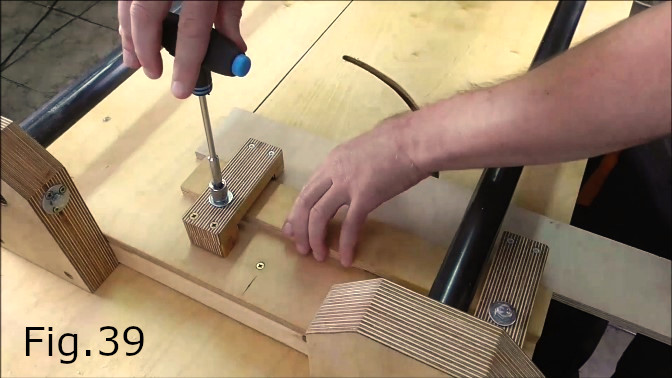
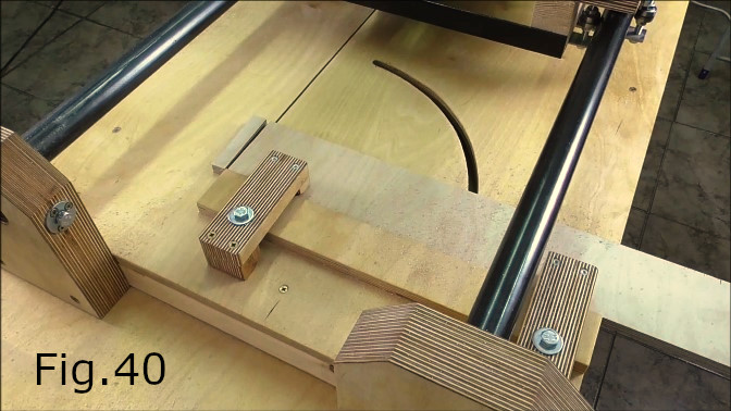
Make some work holding clamps. In figures 39,40,41 and 42 you can see the clamps I made for work holding. The clamps use 100mm M8 bolts to fasten them down. Like in Step 23(Fig.35a,35b) 8mm holes were drilled through the table this time just behind the saw stop in the desired locations and a 12mm spade drill was used to widen the holes for M8 nuts on the underside of the table. The nuts were fixed in place with 15mm x 4mm screws and M10 washers.
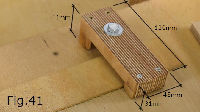
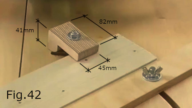
The small work holding clamps seen in Fig.42 are fastened to the table in a different way to the larger clamps seen in Fig.41. The small clamps use the angle guide slot(Fig.38, Fig.42). The M8 bolt is placed through the hole in the clamp and through the angle guide slot with a washer and wing nut fixing the clamp to the underside of the table. For these shape clamps the bolt hole in the clamp itself needs to be elongated, meaning 8mm wide but 15mm long. The elongated holes mean the clamps can be fastened down even when they are not horizontal to the table and fastened at an angle. The clamps were made very quickly and a more effective solution may be to make some clamps from steel that are just as strong as the plywood clamps but have a much lower profile which means you can clamp down thicker material to the table and still have clearance for the saw carriage to pass over the work piece you are cutting. If you just want to use the jig for cutting sheets of plywood (which was the reason I made a crosscut jig) then you probably only need one clamp close to the saw blade and you can use ratchet clamps on the sides of the table to hold the rest of the sheet down.