STEP 1: Cut the Materials to size.
In the the Soap Cutter build video I use a miter saw, circular saw and my circular saw crosscut jig to cut the plywood required. It is best to use sharp circular saw blades with at least 40 teeth so as to produce nice clean cuts and avoid tear out or chipping of the plywood. I used 18mm laminated plywood for the upright pieces and the bridge. But you can use plain plywood the same thickness. Using a different thickness will change the other measurements.
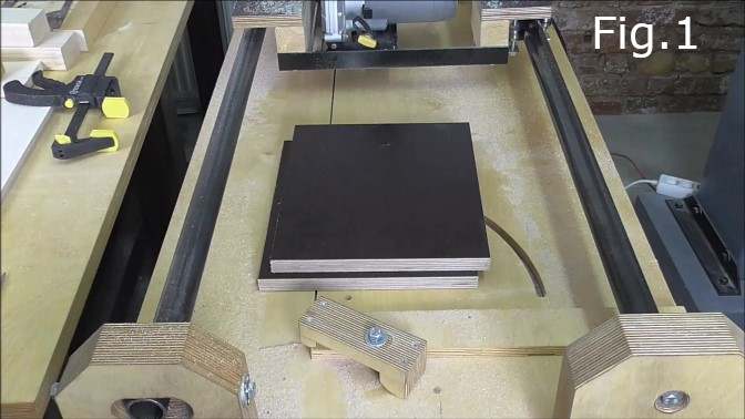
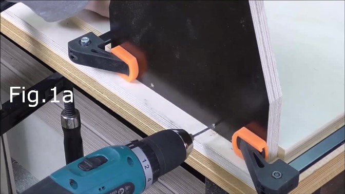
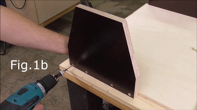
Cutting the plywood required is straight forward apart from the first 2 pieces on the materials list. The pieces for the uprights (fig.1) are 250mm x 230mm. These pieces need to be 250mm at the base and 150mm wide at the top (fig.1b). The angled cuts start 80mm up from the base. So you are cutting a 50mm x 150mm triangle off each side of the upright pieces.
STEP 2: Attach the uprights to the plywood base(above)
Clamp the uprights to either side of the plywood base as seen in fig.1a approx. Drill four screw holes and countersink the holes. I used 4mm diameter screws. Screw the uprights to the base. Screw the middle screws in first then you can release the clamps and screw in the other screws.
STEP 3: Attach the main bridge piece to the uprights.
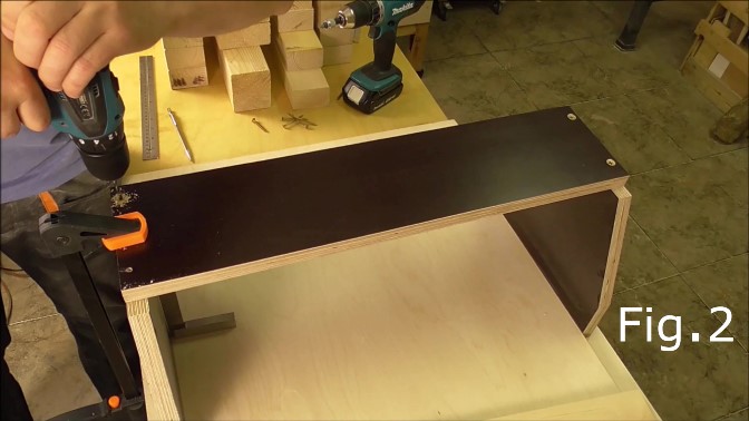
Take the 18mm thick piece of laminated plywood 552mm x 135mm align the piece with the uprights and clamp in place as in fig.2. Make sure the uprights are square to the base. Check with a set square. Set the piece 15mm back from the front edge of the uprights to allow for the 15mm plywood that holds the tuning pegs. Drill and countersink holes as seen in fig.2. Screw the bridge to the uprights.
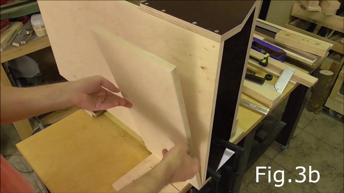
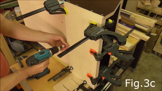
STEP 4: Glue the base support for the uprights.
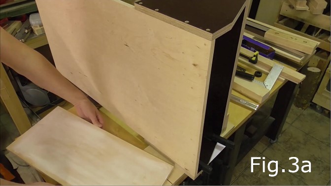
Next take the plain plywood piece 554mm x 250mm. Spread wood glue evenly over the surface(fig.3a), align so its flush and clamp in place(fig.3c).
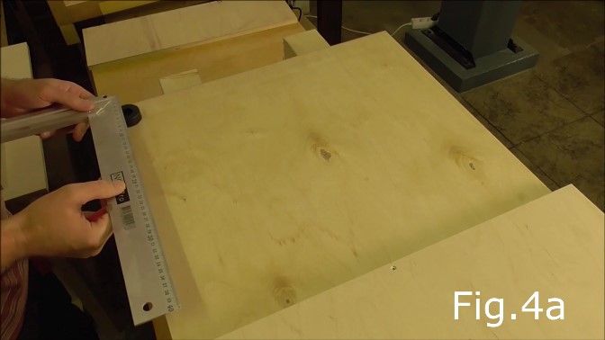
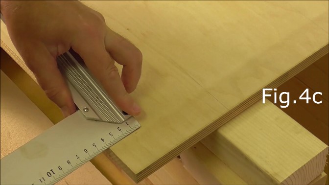
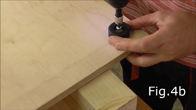
STEP 5: Attach rubber feet.
I had two spare rubber feet which are attached by screws (see fig.4a & 4b). The rubber feet are exactly the same thickness as the 15mm plywood which is glued to the base in step 4. The rubber feet provide support for the base at one end and also stop the soap cutter from sliding around on a work table. If you cannot find 15mm thick rubber feet then you can glue a piece of wood onto the base to make up the difference in thickness and then attach your pads or rubber feet to that piece of wood. The rubber feet are centered in the corners, 40mm from each edge(see fig.4a,4b & 4c).
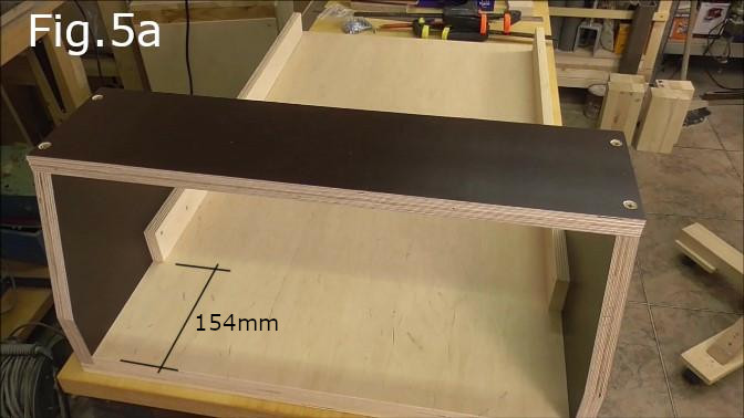
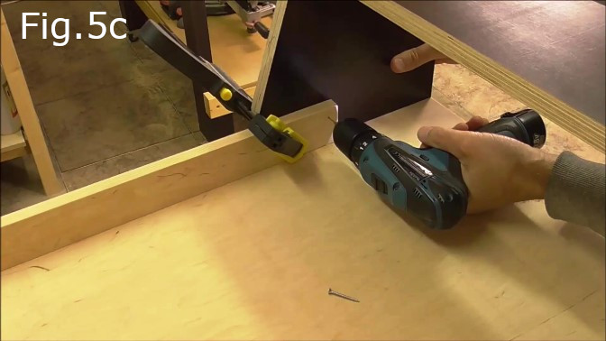
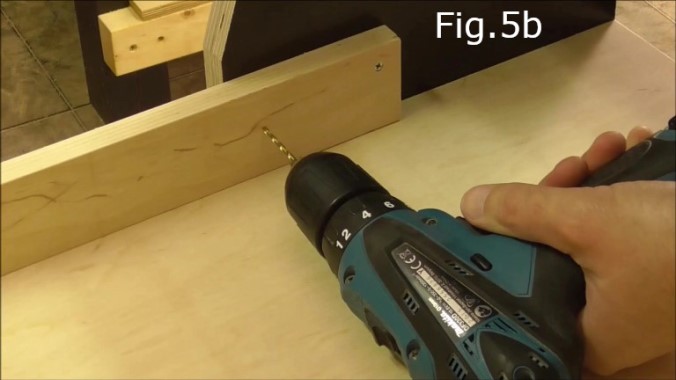
STEP 6: Attach plywood draw slider supports
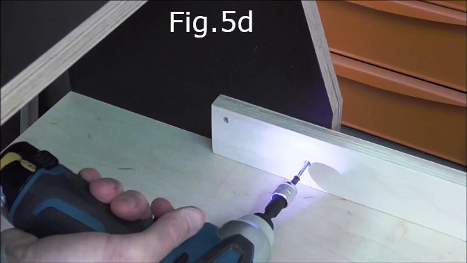
Take the plain plywood pieces that measure 725mm x 50mm and place the ends 154mm from the end of the base board and laminated uprights (see Fig.5a) Clamp each piece to the bridge supports (see Fig.5c) Drill holes for 25 or 30mm screws and countersink (Fig.5b & 5c) Screw the pieces in place (Fig.5d)
STEP 7: Screw the draw slider supports to the base board.
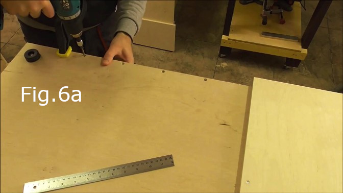
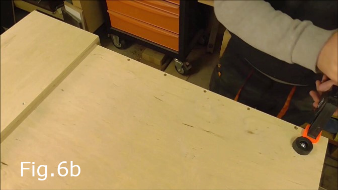
Clamp the draw slide supports seen in Fig.5a,5b,5c and 5d to the base board. Ensure that the supports are clamped straight. Turn the Soap cutter upside down so you can drill and screw the supports from the underside of the cutter (see Fig.6a, 6b) Drill and counter sink holes for at least 5 evenly spaced 40mm long screws. Screw both supports in place.
STEP 8: Cut the string slots in the cutting board.
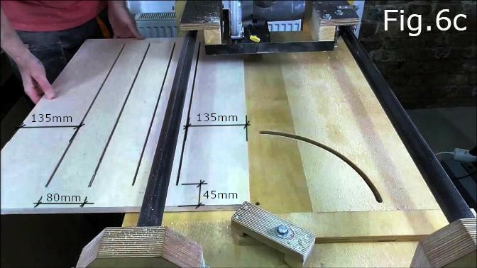
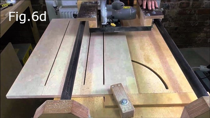
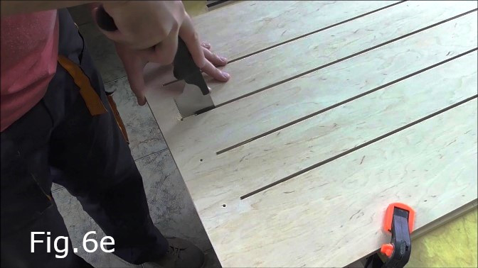
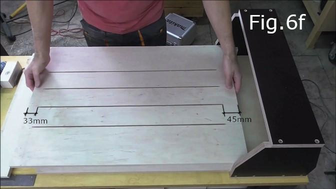
Take the plywood piece 750mm x 513mm x 15mm, this is the cutting board. In my build video I cut the slots using my circular saw crosscut jig and cut the last 50mm of each slot with a hand saw(Fig.6e). However a possibly more accurate method would be to use a router with a 5 or 6mm bit and a straight piece of wood clamped to the cutting board as a guide for the router. The four slots are cut at 80mm centers with the slots centered on the board(Fig.6c) The string slots start 33mm from the back of the board and finish 45mm from the front end(Fig.6f)
STEP 9:
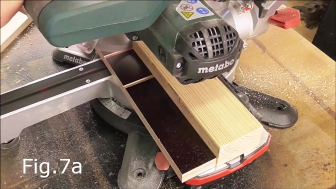
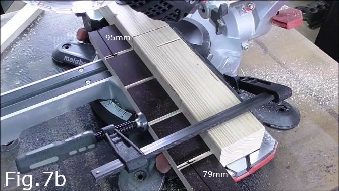
In this step cut approximately 3 to 4mm deep slots (Fig.7a & 7b) in the 414mm x 50mm piece of laminated plywood which acts as a back stop piece against which the soap blocks will rest. The slots enable the steel strings to cut completely through a soap block as its pushed though the cutter. The slots in the back stop should align with the slots in the cutting board at 80mm centers(Fig.9c). The center of the first slot should be 95mm from the end of the back stop piece and the center of the last slot should be 79mm from the other end of the back stop(Fig.7b). The slots in the back stop should be the same width as the slots in the cutting board.
STEP 10:
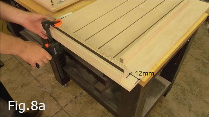
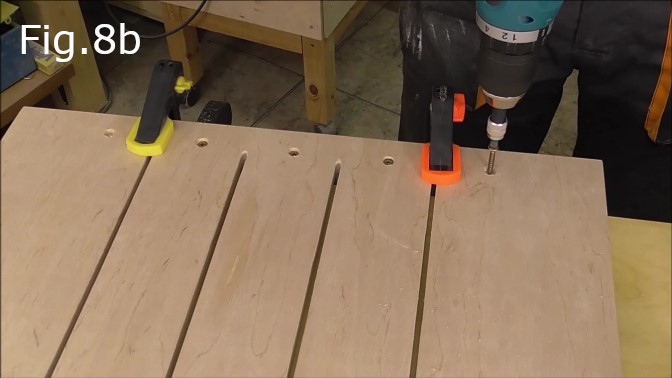
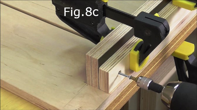
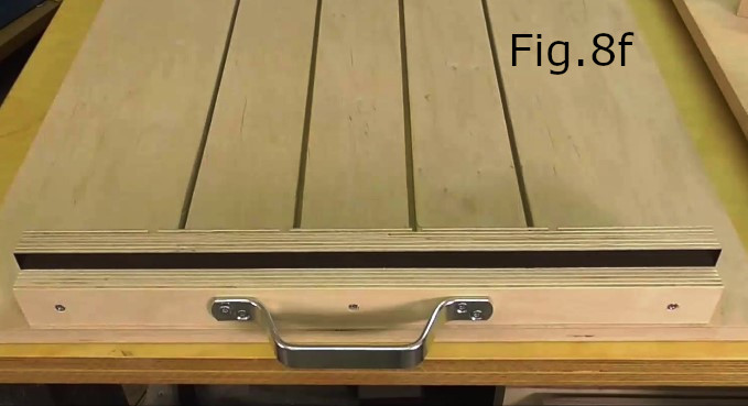
After cutting the slots in the backstop piece screw it to the back end of the cutting board. The back end of the cutting board has the slots finishing 33mm from the end(Fig.6f). The end of the backstop which has the first slot located 95mm from the edge(Fig.7b) is the right side end which should be clamped 42mm from the right side edge of the cutting board(Fig.8a). The slots in the backstop piece should be located so they line up with the end of the cutting board slots so that the cutting strings can push through the soap blocks when finishing a cut. Once the backstop is aligned and clamped in place turn the board over and drill countersunk holes through the cutting board and into the backstop for 5 screws(Fig.8b). Space the screws 80mm apart in between the cutting board slots. Next take the 414mm x 35mm piece of plain plywood and align it so the ends are flush behind the backstop piece(Fig.8c). Clamp in place and drill holes for 3 evenly spaced screws so this piece is fixed to the backstop. One screw in the middle and one at each end(Fig.8f).
STEP 11:
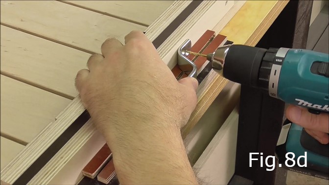
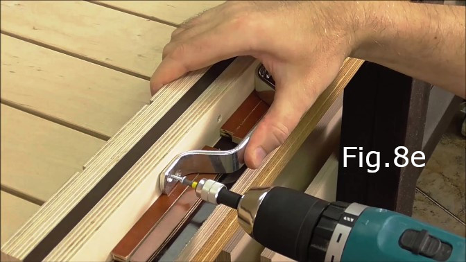
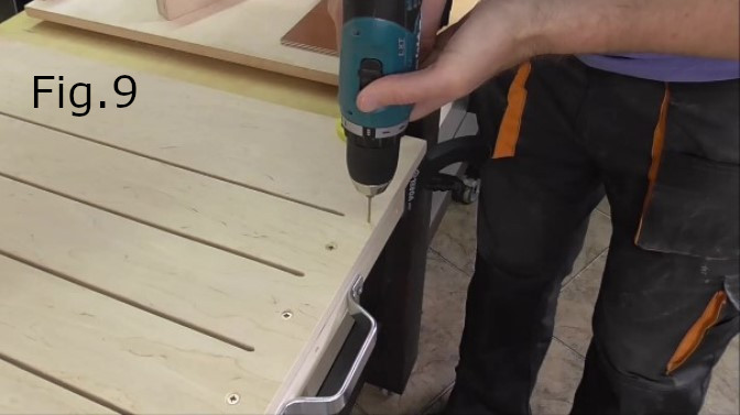
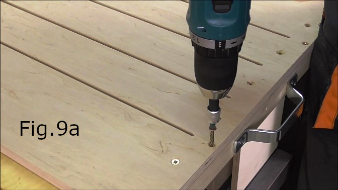
Attach the steel handle. Mark and drill screw holes for the steel handle(Fig.8d). Make sure the handle is aligned so it is centered both vertically and horizontally on the plywood support piece(Fig.8f). Once aligned screw in the handle(Fig.8e). After attaching the handle turn the cutting board over and drill two countersunk holes for screwing the plywood handle support to the cutting board(Fig.9). Be careful to align the screw holes with the center of the plywood handle support piece on the other side of the cutting board. Screw in the screws(Fig.9a).
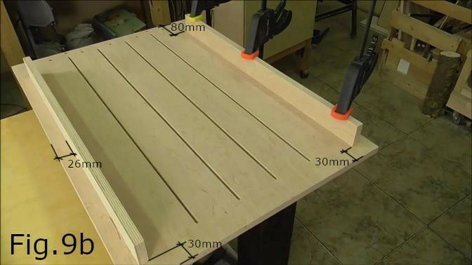
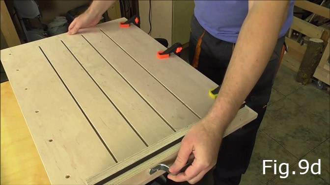
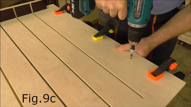
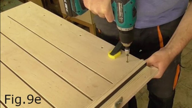
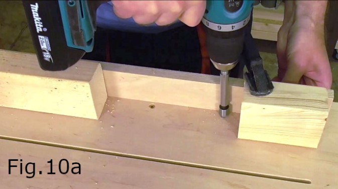
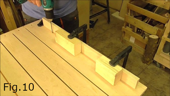
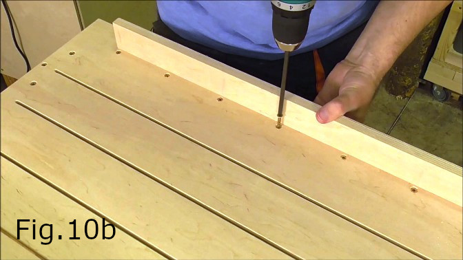
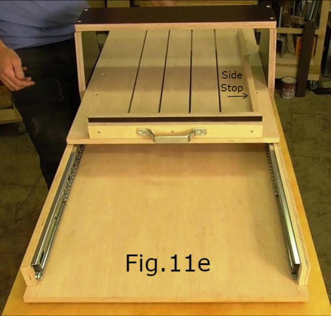
STEP 12: While the cutting board is upside down take the two pieces of 640mm x 50mm plain plywood. These are the draw slider supports for the cutting board. Clamp them in place one at a time, with one end 30mm from the front end of the cutting board and 80mm from the back end of the cutting board where the handle is located(Fig.9b). The outside edges of both pieces are 26mm from the outside edges of the cutting board. Once clamped in place turn the cutting board over then drill and countersink holes for 6 evenly spaced screws(Fig.9c,9d & 9e) for each of the draw slider supports. Next take the 600mm x 30mm plywood piece which is the side stop for aligning soap blocks on the cutting board. Clamp this to the cutting board flush with the backstop exactly 42mm from the right side edge of the cutting board(Fig.11e). The clamping arrangement can be seen in Fig.10. Of course to drill this in place the cutting board needs to be upside down and you will need a long drill bit at least 85mm, adapters to countersink the holes and a long shank screwdriver bit(Fig.10,10a,10b).
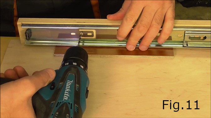
STEP 13: Attach the drawer sliders.
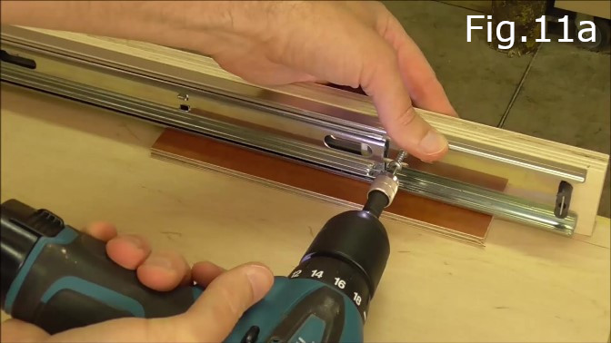
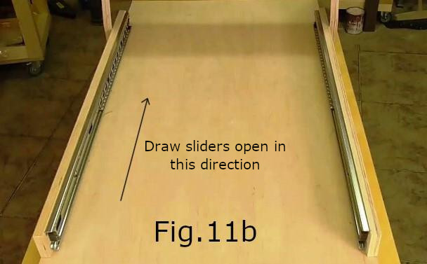
Separate the drawer rails from the cabinet rails of the sliders. Take each slider cabinet rail and place them against the cabinet rail supports(Fig.11) with 6mm spacers under the rail. The cabinet rails should be placed 10mm in from the end of the cabinet rail slider supports(Fig.11a,11b). Drill the holes for the screws. Screw the rails in place.
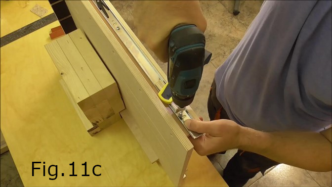
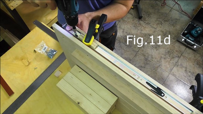
STEP 14:
Next attach the drawer rails of the sliders to the slider supports on the underside of the cutting board(Fig.11c & 11d). The front end of the drawer rails should overhang the front end of the slide supports by 15mm(Fig.11c). The back end of the drawer rails overhang the slider supports by 40mm. These measurements may vary depending on the type of drawer sliders you buy. The main thing is to make sure the cutting board will move so the strings travel at least 600mm through the cutting board slots. Once the rails are in place insert the cutting board into the cabinet rails and check the cutting board travel(Fig.11e) and if needed adjust the location of the drawer rails.
STEP 15:
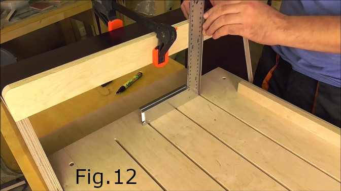
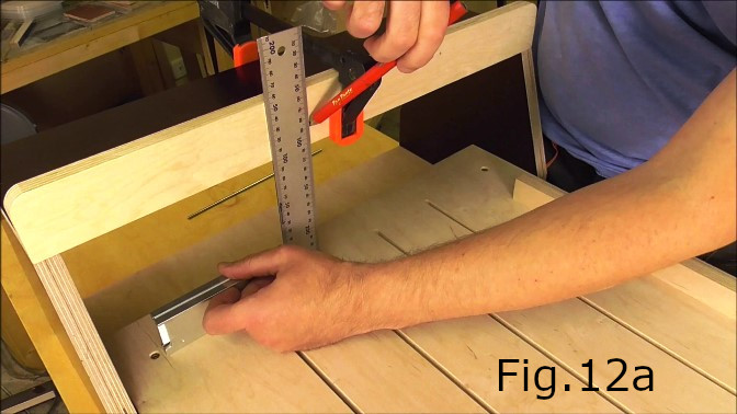
Clamp the 552mm x 55mm piece of plain plywood to the bridge as can be seen in Fig.12. This piece is the tuning peg support piece. To lessen the amount of sharp corners on the cutter I rounded off both the upper corners of this piece on my disc sander(Fig.12a). You can then mark the locations for the tuning peg holes in the support piece. Use a set square to mark a line square with the middle of each of the slots in the cutting board(Fig.12a). The vertical marks for the tuning peg holes should be 80mm apart. Next use a straight piece of steel thin enough to fit through the slots to mark the location for the string anchor point. I used a black felt marker to mark the steel and transfer the mark to the base board making sure to use the square as a guide(Fig.12).
STEP 16:
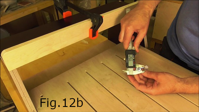
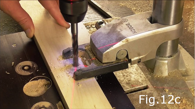
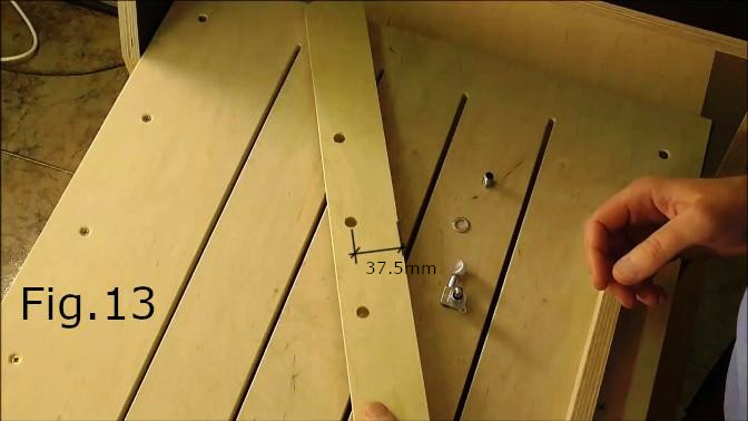
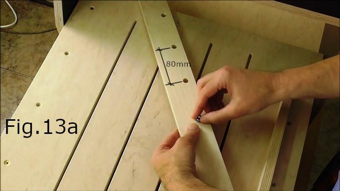
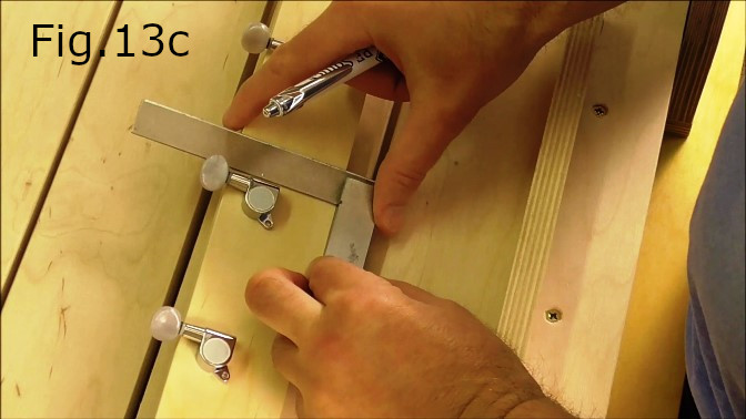
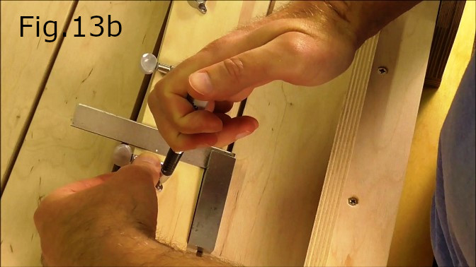
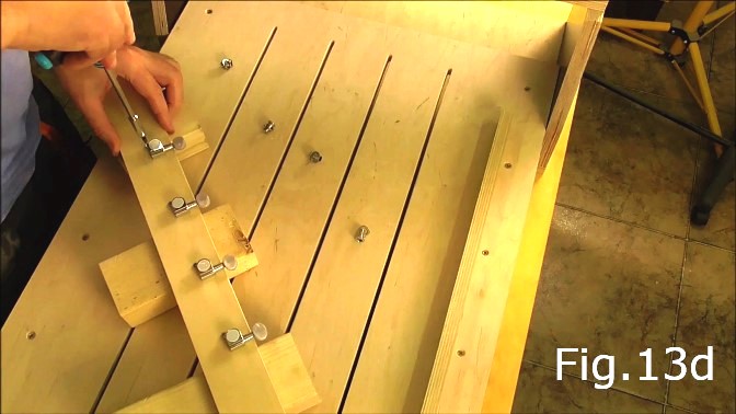
Measure the diameter of the tuning pegs(Fig.12b). The tuning pegs I used had an approximately 10mm diameter. Your tuning pegs may have a larger of smaller diameter. Adjust accordingly. The tuning peg hole centers should each be located 37.5mm from the bottom edge of the support piece(Fig.13). Once the hole positions have been marked. Drill the holes with a bit that matches the diameter of your tuning pegs(Fig.12c). In my case this was a 10mm bit. The holes should be 80mm horizontally between centers(Fig.13a). Fit the tuning pegs in the holes and screw them up tight using a set square to ensure squareness(Fig.13c). Mark the positions for the tuning peg screws(Fig.13b). The tuning peg screws are small so you really only need to drill a starter hole and then the screws can be screwed in by hand(Fig.13d).
STEP 17:
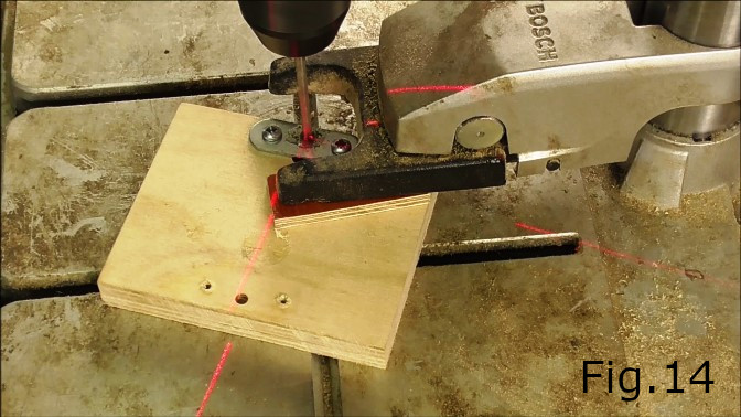
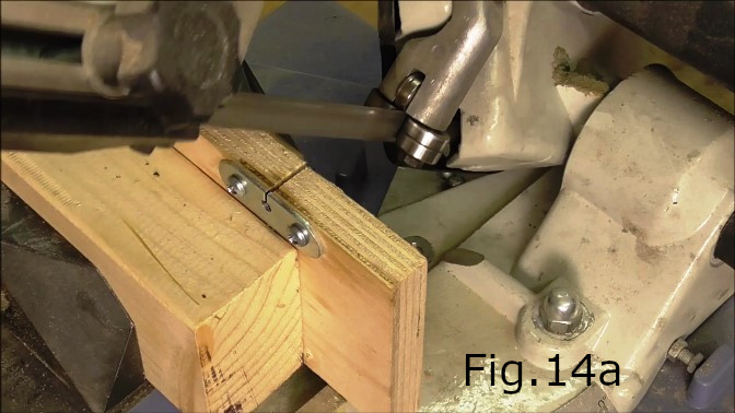
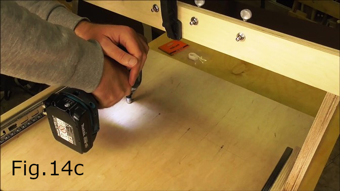
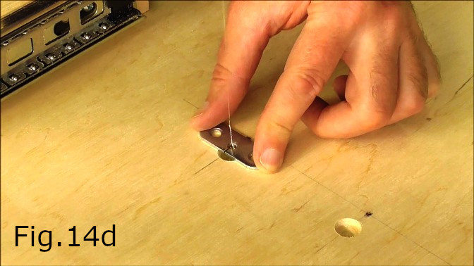
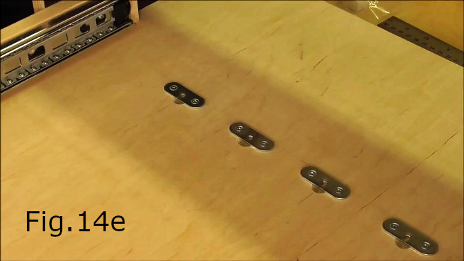
For anchoring the strings to the base board I used flat round end brackets. To accommodate the ball ends of the guitar strings I screwed each bracket to a piece of plywood, drilled a 3mm hole(Fig.14) and then cut through the side of the brackets using the bandsaw(Fig.14a,14b). On the underside of each bracket deburr the string hole with a 4mm drill taking a large enough amount of metal off so the string ball can sit in snug and not move around when fitting the strings. You can test this by sliding the ball end of a string into position as can be seen in Fig.14d. Make sure to deburr the drilled hole on the top side as well but only take a small amount off on the top side of the hole. Ensure the holes are smooth and cannot cut the string with sharp edges when it is in place under tension.
STEP 18:
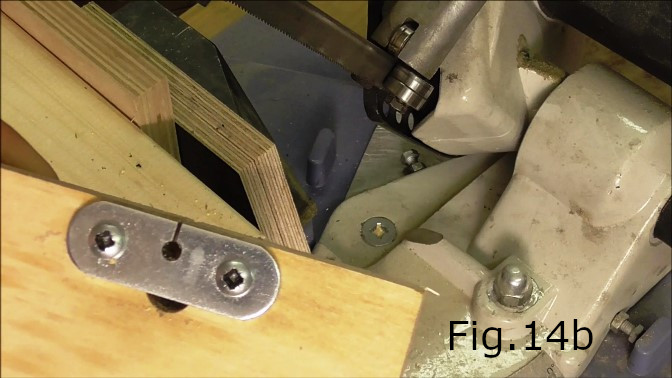
Draw a pencil line through the marks made on the base board in step 15. This line should be parallel to the front edge of the cutter and the bridge. The line can be seen in Fig.14c and 14d. Measure 10mm behind this line towards the back end of the cutter and make a mark for the ball end recesses for each string. The recesses are to enable the string ball ends to fit behind the brackets when fitting the strings. Using a countersink bit create a recess for each string(Fig.14c). Make sure not to drill too deep. Using the previously drawn pencil line visible in Fig.14d as a guide, align the back of all four brackets. Drill starter holes for each bracket screw and screw the brackets in place.
STEP 19:
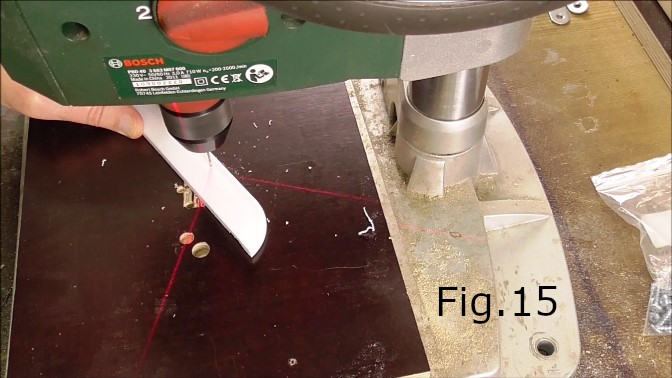
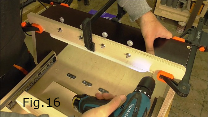
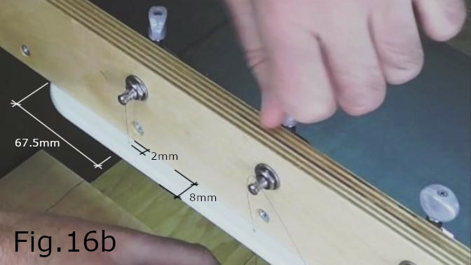
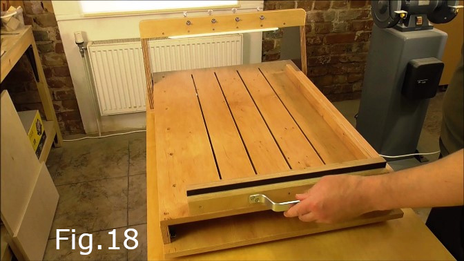
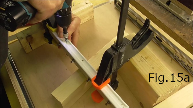
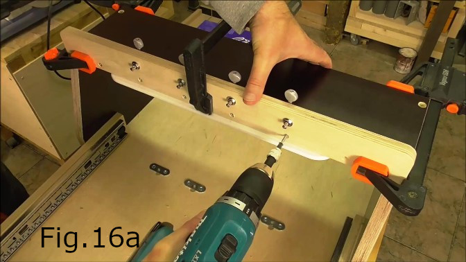
The next step is to make a string guide. I made one by cutting off a piece from a nylon cutting board. The string guide is 375mm in length and 25mm wide or deep. I used a circular saw to cut the nylon. Drill four holes for the strings with the smallest drill bit you can find. I used a 1.5mm bit(Fig.15). The string holes must line up vertically with the locations of the tuning pegs and the middle of the string slots in the main soap cutting board. The first string hole in the guide is 67.5mm from the end of the piece and the last hole should also be 67.5mm from the other end of the string guide so that the holes are centered(Fig.16b). The string holes of course should be 80mm apart, 6mm from the front edge of the string guide. Once the string holes are drilled you can screw the string guide to the underside of the guitar tuner support piece(Fig.15a). Space the five screws out evenly halfway in between each of the tuning pegs. Make sure the string guide protrudes 8mm in front of the tuner support front face(Fig.16b). Once the string guide is screwed to the tuner support, clamp the tuner support piece to the bridge(Fig.16) and drill holes for the screws directly below the tuning pegs and for one screw at either end of the tuner support piece exactly 80mm from the first and last tuning peg(Fig.16,16a &18). Screw the tuner support in place and the bridge is complete.
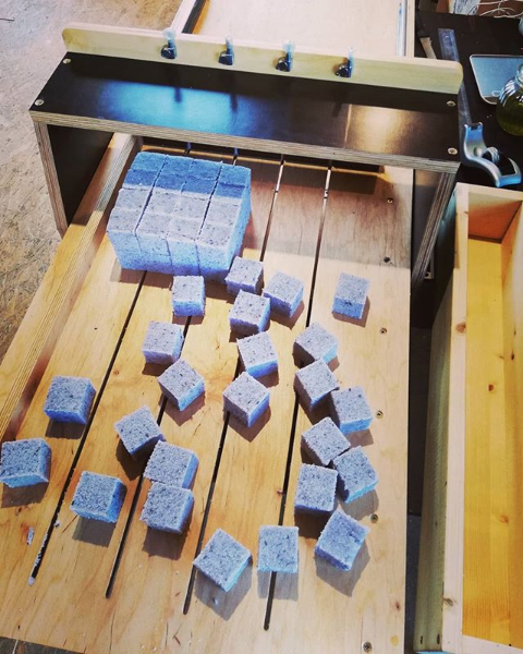
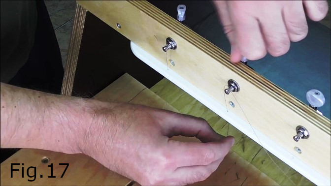
The final step is to thread the strings(Fig.14d & 17). In the video I used quite light gauge strings. But a heavier gauge(PL018-0.018″ or 0.45mm) string would probably be better and last longer. I applied linseed oil to the cutting board and most of the bare plywood surfaces.